Panel Operation
BC-200 Manual
– P/N DOC-01-013
45
7.3.3.11 S
ERVICE
M
ENU
– L
IST
– L
IST
– D
IN
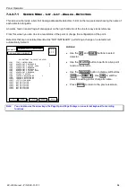
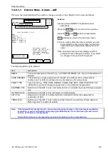
This screen will list all the digital inputs in the system. Digital inputs consist of non-AZF inputs such as fan control
module status inputs and annunciator panel input buttons/switches.
The display shows the point number (Ring.Module.I/O format) and the point description. In addition, the current
state of the point is displayed.
Unnamed points use the associated field module type as their description.
01.010.I1
SPF 1 RUNNING
x
01.010.I2
SPF 1 FAULT
01.010.I3
(FANC)
01.101.I1
BUTTON 1 ON 16AT
01.101.I2
BUTTON 2 ON 16AT
01.101.I3
BUTTON 3 ON 16AT
01.101.I4
BUTTON 4 ON 16AT
01.101.I5
BUTTON 5 ON 16AT
01.101.I6
BUTTON 6 ON 16AT
01.101.I7
BUTTON 7 ON 16AT
01.101.I8
BUTTON 8 ON 16AT
01.101.I9
(ACM16AT)
01.101.I10 (ACM16AT)
01.101.I11 (ACM16AT)
01.101.I12 (ACM16AT)
01.101.I13 (ACM16AT)
01.101.I14 (ACM16AT)
01.101.I15 (ACM16AT)
01.101.I16 (ACM16AT)
DIGITAL INPUT LIST
20 JULY 2002 14:44:37
CHANGE
DOWN
UP
USE UP/DOWN BUTTONS TO SELECT AN I/P:
A = 0
F = 0
I = 0
N = 1
BACK
DAY MODE
Actions:
Use the
UP
and
DOWN
buttons to scroll through
Input points.
Pressing the
CHANGE
button will take you to the
Modify Point Screen (refer to page 61)
Pressing the
BACK
button will return you to the list
menu screen.
In the above example, the following abbreviations of STATUS apply.
Status
Abbreviation
Meaning
I
Isolated
F
Fault
X
Activated
Note:
You can also use the arrow keys, the Page Up and Page Dn keys on an external keyboard for scrolling
functions.
Summary of Contents for BC-200
Page 1: ...BC 200 OPERATION INSTALLATION PROGRAMMING MANUAL P N DOC 01 013 ECN11 0058 23 Aug 12 Rev 5 07 ...
Page 138: ...Appendix BC 200 Manual P N DOC 01 013 138 9 12 PANEL EXPANSION RELAYS ...
Page 142: ...Appendix BC 200 Manual P N DOC 01 013 142 9 9 1 13 3 4 4 R RE EL LA AY Y M MO OD DU UL LE E ...
Page 144: ...Appendix BC 200 Manual P N DOC 01 013 144 9 9 1 13 3 6 6 Z ZO ON NE E M MO OD DU UL LE E ...
Page 155: ......


