Panel Operation
BC-200 Manual
– P/N DOC-01-013
67
7
7
.
.
3
3
.
.
6
6
S
S
E
E
R
R
V
V
I
I
C
C
E
E
M
M
E
E
N
N
U
U
–
–
A
A
N
N
A
A
L
L
O
O
G
G
Overview:
The BC-200 can support up to 4 loops of Analog addressable devices using various protocols including the
Honeywell CLIP protocol, which can support 99 detectors and 99 modules per loop.
On power up, the BC-200 programs the LCMs (Loop Control Modules) with the appropriate information for
devices installed, and then the LCMs handle all the polling of the devices. The LCMs only report off normal
conditions such as alarm, fault etc, to the CPU.
Therefore, if an LCM is for any reason powered down and re-powered, it must be re-programmed to be in
synchronisation with the panel. The BC-200 detects disconnection / reconnection automatically and will re-
program the LCM in the background.
The LCM boards have a slave board that is called the LEM (loop expander module). Two LCM/LEM pairs are
required to achieve 4 loops. Each LCM has an address switch to set the loop address for the pair. While it is not
mandatory that loops always be sequential it is highly recommended for ease of use.
Note:
The Analog menu option contains all functions specific to Analog addressable detectors and modules. Many
of these features can be accessed from previously explained list menus and instructions will not be
duplicated here.
7.3.6.1
S
ERVICE
M
ENU
– A
NALOG
– L
IST
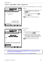
This menu option will list all Analog addressable loops allowing the user to then select detectors or modules and
perform read status and/or change a point’s programming. For a full explanation, please refer to Service Menu –
List – List – Analog on page 33.
7.3.6.2
S
ERVICE
M
ENU
– A
NALOG
– S
TATUS
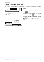
This menu option gives direct access to the read status screen of an Analog addressable point. You will be
prompted for a Loop Number and a Detector or Module number. You will then be taken directly to the Read Status
screen for the point. Please refer to Service Menu – List – List – Analog – Detectors – Status on page 35 or
Service Menu – List – List – Analog – Modules – Status on Page 38
7.3.6.3
S
ERVICE
M
ENU
– A
NALOG
– C
HANGE
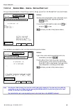
This menu option is direct access to the program / change point screen of an Analog addressable point. You will
be prompted for a loop number and a detector or module number. You will then be taken directly to the program /
change point screen for the point. Please refer to
Service Menu – List – List – Analog – Detectors – Change on page 36 or Service Menu – List – List – Analog –
Modules – Change on page 40.
7.3.6.4
S
ERVICE
M
ENU
– A
NALOG
– R
EMOVE
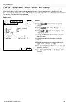
To remove an Analog addressable detector or module from the panel’s memory, it must be removed from the
CPU memory and the LCM memory consecutively. This menu allows for the permanent removal of an Analog
point. You will be prompted for a loop number and a detector or module number. You will then be prompted to
confirm removal by a Yes or No action. If you select YES the detector / module will be permanently removed from
the system.
Summary of Contents for BC-200
Page 1: ...BC 200 OPERATION INSTALLATION PROGRAMMING MANUAL P N DOC 01 013 ECN11 0058 23 Aug 12 Rev 5 07 ...
Page 138: ...Appendix BC 200 Manual P N DOC 01 013 138 9 12 PANEL EXPANSION RELAYS ...
Page 142: ...Appendix BC 200 Manual P N DOC 01 013 142 9 9 1 13 3 4 4 R RE EL LA AY Y M MO OD DU UL LE E ...
Page 144: ...Appendix BC 200 Manual P N DOC 01 013 144 9 9 1 13 3 6 6 Z ZO ON NE E M MO OD DU UL LE E ...
Page 155: ......

