Appendix
BC-200 Manual
– P/N DOC-01-013
97
9.3.1.3
E
VENT
S
OUNDER
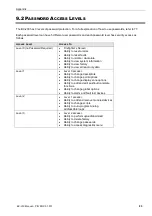
Switch 1 of DIP switch SW1 will enable (ON) or disable (OFF) the buzzer for alarms.
Switch 2 of DIP switch SW1 will enable (ON) or disable (OFF) the buzzer for faults.
If the buzzer is enabled, pressing the “MUTE” button will silence the buzzer until a new event is received.
9.3.1.4
D
ISPLAY
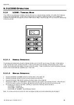
The LCD Display is made up of 4 lines of 20 characters each. Events are displayed as:
In the above example, a fault occurred on the 10
th
September at 12:34pm. It is the first of only one fault and
occurred in the East Wing on point number 1.1.Z3. There are 0 alarms, 1 fault, and 0 isolates on the system.
In this example, an alarm occurred on the 10
th
of September at 12:37pm. It is the first of
two alarms and occurred in the West Wing on point number 1.1.Z7. There are 2 alarms,
2 faults, and 0 isolates on the system.
9.3.1.5
S
PECIAL
M
ESSAGES
ALL SYSTEMS NORMAL
The system is 100% normal with no alarms, faults, or
isolates.
COMMS FAILURE *
This messages flashes and appears when the LCD80 has
not been polled by the CPU in over 10 seconds
CPU NOT RESPONDING
The LCD80 is being polled by the CPU, but the CPU has not
responded to an LCD80 request in over 20 seconds
10 SEPT 12:34
1/1
EAST WING
1.2.Z6
FAULT
*A=0
F=1
I=0
Event No / Total Number of Events
Point Status
Total Isolates
Date Time
Point Description
Point / Zone Number
Comms Indicator
Total Faults
Total Alarms
10 SEPT 12:37
1/2
WEST WING
1.1.Z7
ALARM
*A=2
F=2
I=0
Summary of Contents for BC-200
Page 1: ...BC 200 OPERATION INSTALLATION PROGRAMMING MANUAL P N DOC 01 013 ECN11 0058 23 Aug 12 Rev 5 07 ...
Page 138: ...Appendix BC 200 Manual P N DOC 01 013 138 9 12 PANEL EXPANSION RELAYS ...
Page 142: ...Appendix BC 200 Manual P N DOC 01 013 142 9 9 1 13 3 4 4 R RE EL LA AY Y M MO OD DU UL LE E ...
Page 144: ...Appendix BC 200 Manual P N DOC 01 013 144 9 9 1 13 3 6 6 Z ZO ON NE E M MO OD DU UL LE E ...
Page 155: ......


