background image

2

CM900 Wireless - Programmable Room Thermostat

1) Installation Information

As these products communicate using RF technology special care must be taken during installation. The 

location of the RF components as well as the building structure may influence performance of the RF 

system. To assure system reliability, please review and apply the information given below.

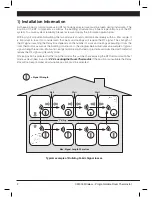
Within a typical residential building the two products should communicate reliably within a 30m range. It 

is important to take into consideration that walls and ceilings will reduce the RF signal. The strength of 

the RF signal reaching the Relay Box depends on the number of walls and ceilings separating it from the 

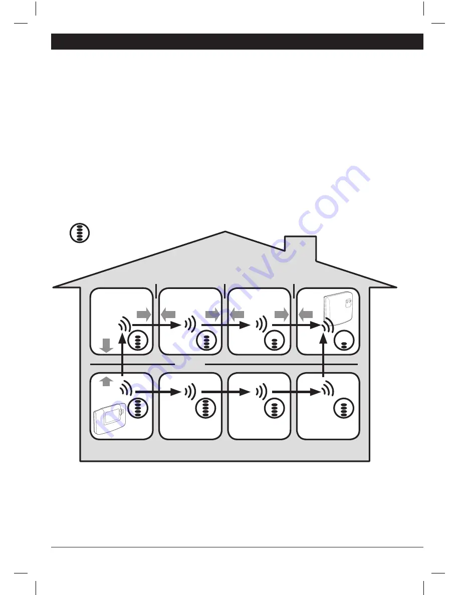
room thermostat, as well as the building construction - the diagram below illustrates an example of typical 

signal strength reduction. Walls and ceilings reinforced with steel or plasterboard walls lined with metal foil 

reduce the RF signal significantly more.

Once a position is selected for the room thermostat this can be checked using the RF Communication Test 

mode as described in section 

2.2.3 Locating the Room Thermostat

. If the position is unsuitable the Relay 

Box will not respond and an alternative position must be selected.

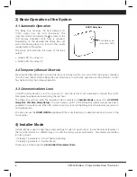
Typical example of Building Fabric Signal losses

Wall

Wall

Wall

Ceiling

Max. Signal Length 30 metres

= Signal Strength

Summary of Contents for BDR91

Page 1: ...ual system packs are separated or mixed with other pre configured system packs during installations please refer to section 5 1 Binding Rebinding Procedure to bind the desired units together and allow them to communicate with each other Table of Contents Section Page 1 Installation Information 2 2 Installing the CM900 Wireless System 3 2 1 Installing the Relay Box 3 2 2 Installing the Room Thermos...

Page 2: ... strength of the RF signal reaching the Relay Box depends on the number of walls and ceilings separating it from the room thermostat as well as the building construction the diagram below illustrates an example of typical signal strength reduction Walls and ceilings reinforced with steel or plasterboard walls lined with metal foil reduce the RF signal significantly more Once a position is selected...

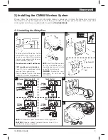
Page 3: ...iance considerations Keep AC mains supply load cables separate from signal wiring Refer to Code of Practice standards EN61000 5 1 and 2 for guidance NOTE The Relay Box contains no user serviceable parts It should be opened and installed by qualified installer only WARNING Electrostatic sensi tive device Do not touch the circuit board NOTE All wiring must be in accordance with IEE regulations CAUTI...

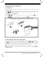
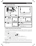
Page 4: ...he green button to confirm 2 2 2 RF Communication Check Test Mode To check the RF communication hold the room thermostat about 2 3 metres from the installed Relay Box Move the slider on the room thermostat to the OFF position then press the and buttons together with the button for 3 seconds The unit will display TEST TRANSMIT and it will send test signals to the Relay Box flashing the green LED on...

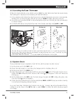
Page 5: ...der switch to the MAN mode 4 Adjust the setpoint up to the maximum 35 C by pressing the button The boiler should come on green LED ON on Relay Box after a few seconds and the symbol appears on the room thermostat LCD display 5 Set the slider switch to the OFF mode The boiler will go off green LED OFF on Relay Box after a few seconds and the symbol disappears 6 Check the system operation by moving ...

Page 6: ...iod of 1 hour the red LED will illuminate to indicate that no RF messages have been received during the last hour The Relay Box will also enter the failsafe mode as selected in Installer Mode see section 4 2 BDR91 Relay Box Fail Safe Mode Setup To allow manual control of the Relay Box output manual override is available in fail safe mode When RF communication is restored the Relay Box will automat...

Page 7: ...o accept the change 6 Attach appropriate label to the Relay Box to indicate the selected fail safe mode IMPORTANT To enable the frost protection when RF communication is lost select the fail safe mode 1 For systems with separate frost protection thermostat or where frost protection is not required select fail safe mode 0 Move the slider switch to the OFF mode Press and hold the button and the two ...

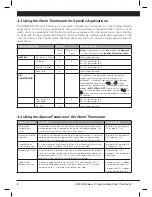
Page 8: ...ature is factory enabled To enable Set parameter 3 tC category 1 to 1 Temperature Offset If the thermostat is located in a particularly hot cold location for reliable signal transmission reasons then the measured displayed temperature can be adjusted by 3 C This is useful if the homeowner wants the reading to match another appliance temperature display Set parameter 12 tO category 1 to the require...

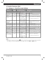
Page 9: ...grammed To restore the factory profile set to 1 Auto Summer Winter Time Change 3 tC 1 Auto Summer Winter Time Change Enabled 0 Auto Summer Winter Time Change Disabled LCD Backlighting 5 bL 1 Backlighting Enable 0 Backlighting Disabled Upper Temp Limit 6 uL 35 35 C Upper Temp Limit 21 to 34 21 C to 34 C adjustment in 1 C steps Lower Temp Limit 7 LL 5 5 C Lower Temp Limit 5 to 21 6 C to 21 C adjustm...

Page 10: ...ed 1 Pump exercise enabled System Synchronisation 6 Sn 0 Standard operation of the Room Unit 1 Room unit configured as Synchroniser Loss of Communications Instruction 7 LC 0 Relay Off 1 Relay 20 on 80 off The following Parameters are for the control of other Honeywell Wireless products such as Wireless Underfloor Heating controls and Wireless Radiator controls For more information please contact H...

Page 11: ... systems and the CM927 921 room thermostat is compatible with a variety of other Honeywell products including HR80 radiator controllers see below and HCE80 underfloor heating controllers If you intend to use it in this way additional installation and user instructions can be obtained by contacting the address at the end of this guide NOTE Some of the labels supplied with the pack are for use in mu...

Page 12: ... LED is on and the green one is flashing once every 3 sec on the Relay Box Incorrect or incomplete binding procedure Incorrect position of the room thermostat during binding Repeat the binding procedure Repeat the binding procedure keeping approx 1 m distance between the Relay Box and the room thermostat The red LED on the Relay Box is illuminated Communication loss The Relay Box receives no RF me...

Reviews: