background image

Bendix/King by Honeywell 

KMA 30 Audio Panel and Intercom System 

Installation and Operator’s Manual 

200-890-5464 

Page 3-7 

 Rev. 1, Aug. 2012 

In 

CREW

 mode, the pilot and copilot are connected to the telephone. The pilot and copilot will have 

transmit capability on the other selected transceiver Com 1 or 2, simply by using their respective PTT 
switch.  

In 

ISO

 intercom mode, when the KMA 30 is in the 

TEL

 mode, the pilot position is in the "Phone Booth." 

Only the pilot will hear the telephone, and only he will be heard. He will also have access to Com 1 or 2, 
and will transmit on that radio using the PTT. All selected audio is provided.  

NOTE 

Because the cell phone uses an intercom circuit, all stations on that circuit will lose intercom capability 
when the cell phone is in use. Intercom conversations will still be present if the cell phone provides side-
tone, or if the audio panel is modified for telephone sidetone. 
Bendix/King does not guarantee compatibility with personal cellular telephones. . 

3.9.1 

Cellular telephone sidetone 

As shipped from the factory, the KMA 30 does NOT provide cellular telephone sidetone (the user’s voice 
fed  back  to  the  headset).  Some  cell  phones  do  not provide sidetone. In the KMA 30 Telephone sidetone 
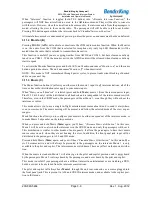
can be enabled by pressing the TEL and ADF buttons for more than one second.  

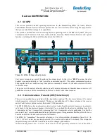
3.10  Utility Jack 

The 2.5-millimeter (3/32”) jack on the front of the KMA 30 has three distinct functions: 


Cell phone input 


Advisory audio input 


Music input 

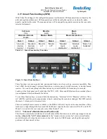
The use of this jack is controlled by three Smart Function Keys (SFK) controlled from the front panel. See 

§ 3.11

 — Smart Function Keys. 

3.10.1  Cellular phone 

When a cellular telephone is connected to this jack using a 2.5 mm to 2.5 mm adapter cord (PS Part Num-
ber 425-006-7026), the KMA 30 audio panel will connect the intercom to the cell phone when the “TEL 
button  is  pressed  (9),  and  behave  as  described  in  section  3.7.    The  telephone  ringer,  if  present,  will  be 
heard unless the input is muted by other radio or intercom. 

3.10.2  Audio Advisory Input 

The front jack can be used as a priority advisory input for auxiliary systems such as a GPS terrain advisory 
or portable traffic watch system. To prevent radio or intercom from muting this input, press the “

Mute

” 

button. 


3.10.2.1 

Smart Jack Function


When the KMA 30 has a signal on music #1 input coming in from the rear connector, the front panel jack 
automatically becomes a Priority Advisory input, and is heard in the crew headphones. 
 

NOTE 

The front jack is no substitute for the certified installation of alerts such as the GPS waypoint or autopilot 
tones. These still must be hard wired into the back by your installer. The front jack input 

will be muted

 by 

radio or intercom unless music is 

actively playing

 in the rear connector. Consequently, it is possible that 

an alert may be missed unless the mute mode is deselected. 

3.10.3 


Music Input 

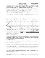
When used as a music input, the front panel jack is treated as Music #1. However, thanks to the function 
controls, it can be distributed to all users, depending on the intercom mode. A patch cord is available with 
2.5 mm to 3.5 mm (3/32 to 1/8”) adapter cord (PS Part Number 425-006-2535). 

Summary of Contents for Bendix/King KMA 30

Page 1: ...0 Document P N 200 890 5464 Rev 1 Aug 2012 Bendix King Inc 2012 Copyright Notice Any reproduction or retransmittal of this publication or any portion thereof without the expressed written permission of Bendix King Inc is strictly prohibited For further information contact the Publications Manager at Phone 865 988 9800 Manufactured for Bendix King a division of Honeywell Int l Inc Albuquerque NM 87...

Page 2: ...CAL NOISE 2 2 2 4 2 EXISTING GMA340 INSTALLATION 2 3 2 4 3 POWER 2 3 2 4 4 AUDIO PANEL INTERFACE 2 3 2 4 5 TRANSMIT INTERLOCK 2 3 2 4 6 BACKLIGHTING 2 4 2 4 7 UNSWITCHED INPUTS 2 4 2 4 8 SWAP MODE 2 4 2 4 9 TEL DUPLEX FUNCTION FOR CELL PHONES 2 5 2 4 10 PUBLIC ADDRESS MODE 2 5 2 4 11 PA MUTE J2 PIN 12 2 7 2 4 12 MISCELLANEOUS LOGIC OUTPUT J2 PIN 18 2 7 2 4 13 AUDIO ACTIVE OUTPUT 2 7 2 5 INTERCOM W...

Page 3: ... 6 3 9 TELEPHONE MODE 9 3 6 3 9 1 CELLULAR TELEPHONE SIDETONE 3 7 3 10 UTILITY JACK 3 7 3 10 1 CELLULAR PHONE 3 7 3 10 2 AUDIO ADVISORY INPUT 3 7 3 10 3 MUSIC INPUT 3 7 3 11 SMART FUNCTION KEYS SFK 3 8 3 11 1 INTERCOM ALTERNATE INTERCOM FUNCTION A 3 8 3 11 2 MONITOR B 3 9 3 11 3 MUSIC C 3 9 3 11 4 MUSIC 1 VOLUME 3 10 3 11 5 POWER ON ANNOUNCEMENT 3 11 3 12 BLUETOOTH INTERFACE 3 11 3 12 1 PAIRING AN...

Page 4: ... Warning Use ofnon aviation approved cellular telephone equipment maybe prohibited byFCC regulation Bendix King is not responsible for unauthorized airborne use of cellular telephones For airborne use the KMA 30 must be interfaced with an approved system There are five unswitched inputs available for traffic or EGPWS autopilot disconnect and or radar al timeter warning with the fifth unswitched in...

Page 5: ...nd Marker Beacon Receivers ED 14C DO 160C Environmental Conditions and Test Procedures for Airborne Equipment ED12B DO 178B Level D Software Considerations for Airborne Equipment and ED 18 DO 214 Audio Systems Characteristics and Minimum Operational Performance Standards for Air craft Audio Systems Operation is subject to the following conditions This device may not cause harmful interference This...

Page 6: ...HD typical Microphone Impedance 150 600 Bluetooth Radio KMA 30 0702 only Class 3 FCC ID QOQWT32AE Intercom Specifications Intercom Positions 6 places with individual IntelliVox circuits Music Inputs 2 Independent Stereo Music Muting 30 dB Soft Mute when Com or intercom active Distortion 1 THD 38 mW into 150 Mic Freq Response 3 dB 300 Hz 6000 Hz Music Freq Response 3 dB 10 Hz 26 kHz MARKER BEACON R...

Page 7: ...2 475 440 0001 Solder Lug 2 475 009 0001 Cable Clamp 1 625 001 0002 6 32 x Flat head Philips screw 6 475 632 0012 6 32 Clip Nut 6 475 630 0002 Table 1 3 Installation Kit Contents 1 7 EQUIPMENT REQUIRED BUT NOT SUPPLIED a Circuit Breaker 1 ea 5 amp PULL TYPE REQUIRED for KMA 30 b Speaker 4 c Headphone Jacks Stereo as Required d Microphone Jacks as Required e Headphones 150 Stereo up to 6 as require...

Page 8: ...e list in Section 1 6 B If any claim is to be made save the shipping mate rial and contact the freight carrier Do NOT return units damaged in shipping to Bendix King If the unit or accessories show any sign of external shipping damage contact Bendix King to arrange for a replace ment Under no circumstances attempt to install a damaged unit in an aircraft Equipment returned to Bendix King for any o...

Page 9: ...dvisory Circular 43 13 2B for more information Failure to use correct techniques may result in improper operation electrical noise or unit failure Damage caused by improper installation will void the Bendix King warranty 2 4 1 Electrical Noise Due to the variety and the high power of radio equipment often found in today s general aviation aircraft there is a potential for both radiated and conduct...

Page 10: ... COM transceivers and a full duplex cellular satellite telephone Added capabilities include IntelliVox DuTel duplex telephone improved music fidelity and Soft Mute and Karaoke muting modes improved and more flexible music distribution control internal recorder function and additional unswitched audio inputs Installations where the external marker outputs are connected to a Sandel 3308 Navigation D...

Page 11: ...il Safe Hear in Crew Headset SPR button Select Gain 1 Yes Yes No 1 1 fixed 2 No Yes Yes 1 1 fixed 3 No Yes No Adjustable 4 No Yes No 1 1 fixed 5 jack No Yes No 1 1 fixed Table 2 2 Unswitched input table Unswitched 2 J1 pin 44 is unswitched is always connected to the Pilot s headphone However this unswitched audio is only presented to the aircraft speaker when the SPR push button has been selected ...

Page 12: ... Bendix King the KMA 30 does provide cellular telephone sidetone the user s voice fed back to the headset Some cell phones already provide sidetone In KMA 30 audio panels Telephone sidetone can be disabled if desired by pressing the TEL and ADF buttons for more than one second NOTE Unauthorized use of unapproved cellular telephone devices in aircraft is subject to FCC enforcement ac tion which may...

Page 13: ...ration jumper J4 MUST be placed across both pins in the header This jumper is shipped as open from the factory 2 4 10 1 Public Address Output Jumper 1 Remove qty 5 Phillip head screws from the PM8000B NOTE THE SCREW IN THE REAR OF THE PANEL IS A DIFFERENT LENGTH THAN THE OTHER FOUR YOU MUST PUT THE SHORTER LENGTH SCREW BACK IN THE SAME LOCATION OR DAMAGE WILL OCCUR See Figure 1 Figure 2 2 Screw Lo...

Page 14: ...ix C and D for intercom connection configurations It is critical to the proper operation of this system to have this connector wiring made in accordance with these diagrams Use 2 and 3 conductor MIL spec cable as shown Connect the shields at the audio panel end only and tie to the audio low inputs as shown 2 5 1 Entertainment Inputs The KMA 30 has two INDEPENDENT music inputs PLUS a front mounted ...

Page 15: ...ent ICS mode dependent and single input music 1 to all stations If the inputs are independent Input 1 or the front jack is provided to the pilot and copilot Muting SoftMute is controlled by the front panel mute button Music 2 is provided to the passengers at all times with muting controlled by an external switch see 2 5 2 1 If the inputs are intercom mode dependent input 1 goes to the pilot copilo...

Page 16: ...n will not operate during the test mode This output will go to 4 5 VDC 1 0 VDC when a valid Middle Marker signal is received This output is J1 pin 39 2 7 Adjustments The KMA 30 is factory adjusted to accommodate the typical requirements for most aircraft configurations There are three adjustments in the top cover that allow the installer to tailor the specific functions Figure 2 4 KMA 30 Adjustmen...

Page 17: ...ed that the one VHF communications antenna is lo cated on top of the aircraft while the other communications antenna is installed on the bottom Any an tenna relocation must be accomplished in accordance with AC 43 13 2B aircraft manufacturers recom mendations and FAA approved technical data WARNING It is probable that radio interference will occur in the split mode when the frequencies of the two ...

Page 18: ...v 1 Audio Low 18 Misc AUX logic output 19 Nav 2 Audio 19 PA Enable Output 20 Nav 2 Audio Low 20 Swap 21 DME Audio 21 Swap Low 22 DME Audio Low 22 IRS Playback 23 Auxiliary Audio Input 23 Music 1 L 24 CNX80 Inhibit 24 Music 1 R 25 No connect 25 Music 1 Low 26 No connect 26 Music 2 L 27 Com 2 Speaker Load 27 Music 2 R 28 Com 2 Speaker Load 28 Music 2 Low 29 Unswitched Audio 3 29 No Connect 30 Com 2 ...

Page 19: ...unning in a hangar This is normal 1 Apply power to the aircraft and avionics 2 Plug headsets into the pilot copilot and occupied passenger positions 3 Verify fail safe operation by receiving and transmitting on com 1 from the pilot position with the audio panel power off The Com audio will be present in one ear cup only 4 Switch on the unit by pressing the volume VOL knob 5 Check intercom operatio...

Page 20: ...local frequency such as FSS or ATC ground Select Com 1 on mic selector switch and record several incoming radio transmissions Press the Com receiver pushbutton that corresponds to the selected radio transmitter and hold for ap proximately one second This action will then automatically play back the last recorded message Press and HOLD the button again to stop the play back and then momentarily pre...

Page 21: ...nel functions intercom and marker beacon receiver All pushbutton selections will be remembered and return to the last state when turned on 3 2 Communications Transmit XMT Selection 2 There are two pushbuttons associated with the transmitter selection The two lower buttons 2 control which transceiver is selected for transmit The top row of pushbuttons 3 allows selection of the receiver audio Push t...

Page 22: ... indicate that the intercom is not muted and the crew can speak to each other 3 2 1 2 Swap Mode Switch from Com 1 to Com 2 remotely With a yoke mounted normally open momentary switch the pilot can change from the current Com transceiver to the other by depressing this switch To cancel Swap Mode the pilot may either press the yoke mounted switch again or select a different Com with the XMT buttons ...

Page 23: ... the speaker button position Depending on installation important audio annunciations such as radar altimeter or autopilot disconnect will come over the speaker even if it is not selected while other unswitched but muted inputs such as GPS alerts will only be present if the SPR button is selected Consult your professional avionics installer for these important configuration details 3 5 1 1 Public A...

Page 24: ...inuous tones therefore people humming or whistling in monotone may be blocked after a few moments For consistent performance any headset microphone must be placed within inch of your lips prefera bly against them ref RTCA DO 214 1 3 1 1 a NOTE It is also a good idea to keep the microphone out of a direct wind path Moving your head through a vent air stream may cause the IntelliVox to open momentar...

Page 25: ... See 3 8 1 ALL All parties will hear the aircraft radio and intercom Crew and passengers will hear selected enter tainment During any radio or intercom communications the music volume automatically decreases The music volume increases gradually back to the original level after communications have been completed CREW Pilot and copilot are connected on one intercom channel and have exclusive access ...

Page 26: ...t panel input their Karaoke Mode is controlled by the front panel Mute button If the passengers are listening to the music 2 input their Karaoke Mode is activated by an external switch installed either in the panel or connected to the AUX button logic output pin on the KMA 30 3 8 1 Music in Pilot ISO mode If desired the pilot can elect to hear Music 1 in the ISO mode While the intercom is in ISO m...

Page 27: ...e use of this jack is controlled by three Smart Function Keys SFK controlled from the front panel See 3 11 Smart Function Keys 3 10 1 Cellular phone When a cellular telephone is connected to this jack using a 2 5 mm to 2 5 mm adapter cord PS Part Num ber 425 006 7026 the KMA 30 audio panel will connect the intercom to the cell phone when the TEL button is pressed 9 and behave as described in secti...

Page 28: ... panel s primary function as a selector panel aircraft intercom or marker beacon receiver You can t do anything with these buttons to prevent the KMA 30 from doing its main job Looking at the front panel you ll notice that the TEL AUX Mute and SPR buttons have secondary func tion assignments listed underneath the button To use these function keys press and hold the desired key Intercom TEL Monitor...

Page 29: ...e rear connector input Pins J2 23 24 only will be distributed to all headsets and is independent of the intercom mode switch Therefore even in the CREW mode the passengers will hear Music 1 even though they will not hear the intercom or radios This mode allows you to use a single in flight entertainment source aboard and to send it everywhere even in crew mode The music muting will be normal and f...

Page 30: ... Crew ISO All Crew ISO Front Panel Jack Crew Crew Copilot Crew Pass Crew Copilot Pass Crew Crew Copilot Music 1 Input Crew Crew Copilot Crew Pass Crew Copilot Pass Crew Pass Crew Pass Copilot Pass Music 2 Input Pass Pass Pass Pass Pilot has Music 1 option in ISO mode Table 3 4 Music Distribution Alternate Music distribution modes are announced at power up unless the power on announcement has been ...

Page 31: ...the KMA 30 you may simply need to re pair 3 12 1 1 Paring separate music and telephone devices It is possible to use a different music source iPad iPod with Bluetooth adapter Bluetooth enabled laptop etc and telephone However the music source must be paired first before the telephone if the telephone also has music streaming capability Otherwise the Smartphone will also take over the music streami...

Page 32: ...tion and Operator s Manual 200 890 5464 Page 3 12 Rev 1 Aug 2012 back will stop whenever there is more incoming selected com audio and the message can be replayed from the beginning by pressing the selected Com Receive button again for 1 second Figure 3 4 Playback Controls ...

Page 33: ...ct or negli gence after Product shipment to Buyer 4 damage caused by failure of a Seller supplied Product not un der warranty or by any hardware or software not supplied by Seller 5 use of counterfeit or replacement parts that are neither manufactured nor approved by Seller for use in Seller manufactured Products 6 products not manufactured by Honeywell but manufacturer s warranty is passed throug...

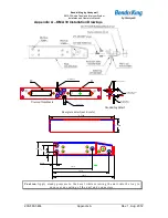
Page 34: ...m Back 15 30 44 1 16 31 15 30 44 1 16 31 Ground Lug Ground Lug 475 440 0001 x2 Back plate assy 475 009 0001 ground lug x2 475 440 0001 x2 Screw w washer Ground lug detail Rear plate detail not to scale 0 37in 3 87in 5 53in 6 04in 0 36in 0 96in 1 28 in 6 31in 1 28in Caution Apply steady pressure to the bezel while screwing the unit into the tray to ensure even seating of the unit and connectors ...

Page 35: ...ighting 22 AWG other wires minimum 24 AWG 3 All mic and headphone jacks must be isolated from ground 4 Speaker loads may be required on some older transceivers Consult manufacturer s information COM 2 Speaker load is the only one provided in the KMA 30 5 All shielded wires must be MIL 22750 or 27500 6 Unswitched inputs 1 is always presented to speaker and crew headphones regardless of SPR switch o...

Page 36: ...minimum 24 AWG 2 All shields should be grounded at audio panel only other end remains floating 3 Pins 8 and 9 connected through a 5 A breaker 4 PA Mute is a TTL level logic output that is pulled low when radio PTT active for external systems 5 All shielded wires must be MIL 22750 or 27500 6 Optional switch to remotely activate playback 7 For music distribution information see Section 2 5 1 8 Pin 1...

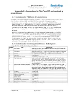
Page 37: ...on dated is placed in the air craft records All work accomplished listed on Work Order 8 2 Instructions for Continuing Airworthiness Audio System Sample ICA Checklist for Bendix King Audio System Section Item Information 1 Introduction Installation of Audio Panel with integrated marker beacon receiver and inter communications system 2 Description Installation as described in manufacturer s install...

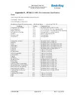
Page 38: ...hock 7 0 Equipment tested to Operational test only Operational 7 2 Equipment tested to Operational test only Crash Safety 7 3 Equipment tested to Operational test only Vibration 8 0 Equipment tested to Category M N Explosion 9 0 Category X not tested Waterproofness 10 0 Category X not tested Fluids Susceptibility 11 0 Category X not tested Sand and Dust 12 0 Category X not tested Fungus 13 0 Categ...

Reviews: