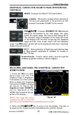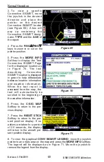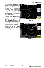
58
Revision 6 Feb/2009
KMD 550/850 FIS Addendum
Normal Operation
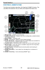
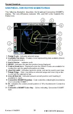
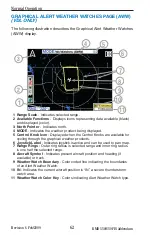
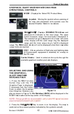
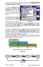
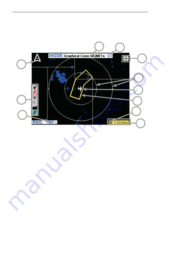
GRAPHICAL CONVECTIVE SIGMETS PAGE
The following illustration describes the Graphical Convective SIGMETs
display. The only difference between VDL and XM is the Datalink Wx
Status icon.
1 Ran
g
e
S
cale
- Indic
a
te
s
s
elected r
a
nge.
2 Available Function
s
- Di
s
pl
a
y
s
icon
s
repre
s
enting d
a
t
a
a
v
a
il
ab
le (
b
l
a
ck)
a
nd di
s
pl
a
yed (color).
3
North Pointer
- Indic
a
te
s
north.
4 MODE
- Indic
a
te
s
the we
a
ther prod
u
ct
b
eing di
s
pl
a
yed.
5 Control Knob Icon
- Di
s
pl
a
yed when the Control Kno
bs
a
re
a
v
a
il
ab
le for
cycling thro
u
gh the gr
a
phic
a
l we
a
ther prod
u
ct
s
.
6 Joy
s
tick Label
- Indic
a
te
s
joy
s
tick i
s
a
ctive
a
nd c
a
n
b
e
us
ed to p
a
n m
a
p.
7 Ran
g
e Rin
gs
- O
u
ter ring r
a
di
us
i
s
s
elected r
a
nge
a
nd inner ring r
a
di
us
i
s
one h
a
lf the
s
elected r
a
nge.
8
Aircraft
S
ymbol
- Indic
a
te
s
pre
s
ent
a
ircr
a
ft po
s
ition
a
nd he
a
ding (if
a
v
a
il
ab
le) or tr
a
ck.
9 Convective
S
IGMET Boundary
- Color coded line indic
a
ting the
b
o
u
nd
a
rie
s
of
a
Convective
S
IGMET.
10 IN
- Indic
a
te
s
the c
u
rrent
a
ircr
a
ft po
s
ition i
s
“
IN
”
a
th
u
nder
s
torm Convective
S
IGMET.
11 Convective
S
IGMET Color Key
- Color
s
indic
a
ting Convective
S
IGMET
type.
4
2
9
6
5
1
3
7
8
10
11

