KTA 970/KMH 980 Pilot’s Guide
Rev 2
006-18273-0000
21
TCAS I Controls and Displays
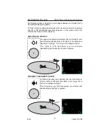
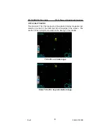
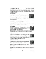
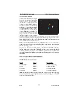
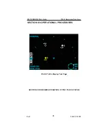
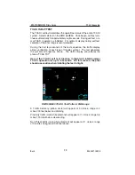
TCAS I ONLY MODE
In this mode the screen’s origin
point is 1/3 up from the bottom
of the screen. Only TCAS I
information is displayed. This
mode is maintained unless
another mode is manually
selected. The range displayed
is that selected on the TCAS I
control panel. A 2 nm range
ring is displayed on ranges 3, 5,
10, and 15 nm. The 2 nm range
ring consists of discrete dots
(cyan) at each of the 12 clock
positions. The 2 nm range ring is not displayed on ranges 20 and 40 nm;
instead, a half-range ring is displayed. The half-range ring consists of dis-
crete dashes (cyan). The TCAS I operational mode is annunciated in the
lower left hand corner of the screen.
Note:
On the “TCAS ONLY” display “WX ON” will be annunciated in the
upper right hand corner if the weather radar is transmitting. See Weather
Radar operating guide.
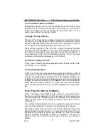
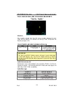
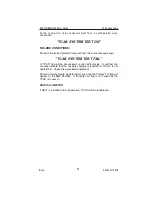
At power-up the screen initially displays the Radar with TCAS I Overlay
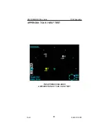
mode. When the Test mode is selected on the TCAS I control panel the
self test pattern is displayed unless TCAS I system failures are detected.
If system failures are detected the screen is blanked and a list of faults is
displayed.
WX & TCAS I MESSAGE FORMATS
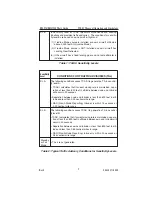
TCAS I Mode Annunciations:
TEXT
Color
Description
TCAS STBY
(Blue)
TCAS I in Standby
TEST
(Blue)
TCAS I in TEST
TA ONLY
(Blue)
TA ONLY Mode
TA AUTO
(Blue)
TA ONLY Pop-Up
Note:
When the Radar is placed in Standby, the TCAS I mode annuncia-
tion is moved to the upper right hand corner and the display is in the WX
only or TCAS I/WX modes.
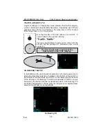
RNG 5
TA ONLY
-05
+25

