Honeywell BW GasAlertMicro, User Manual
The Honeywell BW GasAlertMicro is an advanced gas detection device designed to keep you safe. Access the comprehensive User Manual to fully understand its features, settings, and maintenance procedures. Download the manual for free from our website, ensuring you have the necessary knowledge to operate your GasAlertMicro effectively and confidently.
Share
Download


Reviews:
No comments
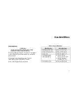
Related manuals for BW GasAlertMicro

7201
Brand: Eastern Energy Pages: 2

MRLDS-450
Brand: Eaton Pages: 9

PDM
Brand: WatchGas Pages: 13

GSX Series
Brand: Watts Pages: 8

GMI PS200 Series
Brand: 3M Pages: 2

110XLS Series
Brand: 3M Pages: 33

H25-IR
Brand: Bacharach Pages: 4

Leakator 10
Brand: Bacharach Pages: 24

HGM300
Brand: Bacharach Pages: 8

DAT 420
Brand: DALEMANS Pages: 17

DAT 420
Brand: DALEMANS Pages: 20

U-H1
Brand: DALEMANS Pages: 40

GD-3000
Brand: Eagle Eye Power Solutions Pages: 24

P21
Brand: FantiniCosmi Pages: 8

Multi Gas Clip
Brand: Gas Clip Technologies Pages: 2

Observer-i
Brand: GASSONIC Pages: 37

GD
Brand: Samon Pages: 8

69310
Brand: yellow jacket Pages: 3


