Page 67
1 Dec 2003
34-45-4
7
MAINTENANCE MANUAL
CAS-100 COLLISION AVOIDANCE SYSTEM
Use or disclosure of information on this page is subject to the restrictions in the proprietary notice of this document.
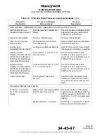
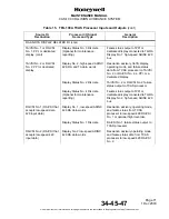
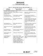
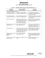
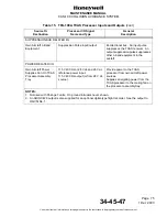
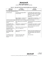
Table 15. TPA-100A TCAS Processor Inputs and Outputs
Source Or
Destination
Processor I/O Signal
Name and Type
General
Description
TCAS ANTENNA RELATED I/O
Directional Antenna
Top and bottom directional antenna.
Four rf, bi-directional, transmit/
receive channels.
1030-MHz differential phase shift
keying modulated TCAS transmit
messages from the TCAS processor
to the directional antenna and
1090-MHz received messages from
the directional antenna to the TCAS
processor.
Bottom TCAS Omni
Antenna
Bottom Omni Antenna. One rf,
bi-directional, transmit/receive
channel. (Same channel as the
element No. 1 port used for the
directional antenna.)
1030-MHz differential phase shift
keying modulated transmit messages
from TCAS processor to omni
antenna and 1090-MHz received
messages from the omni antenna to
TCAS processor.
Three Strapped Pins on
Processor Rear
Connector
Antenna Delay Straps. Three
discretes.
Supply calibration data base inputs to
TCAS processor to adjust for the
difference in the cable lengths
between top and bottom antenna.
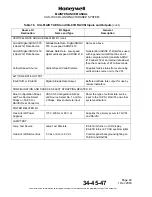
MODE S TRANSPONDER RELATED I/O
Mode S Transponder
No. 1 and No. 2
Coordination Data. 429 high-speed,
transmit bus and ARINC 429
high-speed receive bus.
ARINC Real-time and periodic data
from TCAS processor to the
transponder includes TCAS
equipment and control change data.
Real time and periodic data from
transponder to processor. The data
from the transponder to the
processor includes TCAS control,
own barometric altitude, own
identification, own maximum
airspeed, broadcast and coordination
data. If the ADS-B program pin is
strapped, TCAS will request own
position and velocity data from the
transponder.
Strap Pin on Processor
Rear Connector
Discrete input from Transponder
Interface Select Strap
Tells TCAS processor if one or two
transponders are installed.


