background image

EAGLE CONTROLLER – INSTALLATION & COMMISSIONING INSTRUCTIONS 

 19 

EN1Z-0970GE51 

R1112 

PANEL BUS CONNECTION 

The EAGLE Controller features two RS485 interfaces to which Panel Bus modules can be connected: RS485-1 (consisting of 
push-in terminals 24 [GND-1], 25, and 26) and/or RS485-2 (consisting of push-in terminals 29, 30, and 31 [GND-2]). 

NOTE:


GND-2 is internally connected with 24V-0 (terminal 1) and system GND (terminals 19+37) 


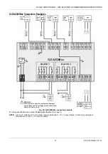
Overview of Panel Bus I/O Modules 

XS821-22

XSU821-22

XS823

XSU823

XS824-25

XSU824-25

EAGLE

PANEL BUS

PANEL BUS

PANEL BUS

PANEL BUS

PANEL BUS I/O

ELECTRONIC

MODULES

pluggable

ANALOG OUTPUT

pluggable

ANALOG INPUT

pluggable

BINARY INPUT

pluggable

FLOATING

OUTPUT

CLIOP821A

CLIOPR822A

CLIOP822A

CLIOP823A

pluggable

RELAY OUTPUT

CLIOPR824A

CLIOPR825A

CLIOP824A

MIXED I/Os

(with integrated electronic module)

1 2 3 4 5 6 7 8 9 10 11 12

B1

B2

B3

B4

B5

B6

B12

12

6

B11

11

5

B10

10

4

B9

9

3

B8

8

2

B7

7

1

DI

Binary Inputs

G1

G2

41

42

GND Analog Outputs

AI2 AI3

AI4

14

15

16

AI1

17

18

19

20

13

Analog Inputs

AO5

AO1

AO6

AO2

AO7

AO3

AO8

AO4

21

25

26

27

28

22

23

24

DO

24V Relays

NO1 NO2 NO3 NO4 NO5 NO6

CO1 CO2 CO3 CO4 CO5 CO6

35

29

30

31

32

33

34

36

37

38

39

40

1 2 3 4 5 6

Install. Instr.

MU1B-0473GE51

!

AI5 AI6 AI7

AI8

Honeywell

CLIOP830A

CLIOP830A (w/ bridge connector)

or CLIOP831A (w/ wiring)

CLIOP831A


Fig. 28. Overview of Panel Bus I/O Modules 


Considerations 


RS485-1 (isolated) 

-

  Max. Panel Bus length: 800-1200 meters, depending on baud rate (see section “RS485 Standard” on pg. 8) 


RS485-2 (non-isolated) 

-

  Max. Panel Bus length: 40 meters 

-

  Any type of cabling and topology possible (preferably twisted-pair cable and bus topology) 

-

  Must not extend beyond a single building or building floor 


Max. no. of Panel Bus I/O modules per RS485 interface


-

  Max. no. of Panel Bus I/O modules of a given model: 16 

-

  Total max. no. of Panel Bus I/O modules: 64 


Max. no. of Panel Bus I/O modules per EAGLE 

-

  Max. no. of Panel Bus I/O modules of a given model: 32 

-

  Total max. no. of Panel Bus I/O modules: 128 


Max. no. of hardware I/O NVs per EAGLE: 600


-

  Max. no. of mapped NVs allowed per EAGLE is thus 600 minus the no. of hardware I/O points. 

 
Refer to CentraLine I/O Modules - Installation & Commissioning Instructions (EN1Z-0973GE51) for more information about 
connection, current requirements, power supply, overvoltage protection, cable specifications, fusing, effects of manual overrides, 
etc. of Panel Bus I/O modules and field devices connected to them. 
 

Summary of Contents for Centra Line CLEA2000B01

Page 1: ...xamples 13 Internal I Os of the EAGLE 15 Engineering Commissioning 17 Required Preparations 17 Extra Parts 18 Panel Bus Connection 19 Considerations 19 Connecting RS485 1 to Panel Buses 20 Connecting RS485 2 to Panel Buses 21 Cable Specifications 22 BACnet MS TP Bus Connection 23 Considerations 23 Connecting RS485 1 to BACnet MS TP Buses 23 Connecting RS485 2 to BACnet MS TP Buses 24 Troubleshooti...

Page 2: ...d Use only accessory equipment which comes from or has been approved by Honeywell Information as per EN 60730 Purpose The EAGLE Controller is a multifunctional non safety control device intended for HVAC in home residential commercial and light industrial environments Construction The EAGLE Controller is an independently mounted electronic control unit with fixed wiring Mounting Method The EAGLE C...

Page 3: ...p slow BI 400 m 2 2 BI open 24 V closed 2 0 mA totalizer 15 Hz 400 m 4 4 4 4 AO 0 11 V max 1 mA 400 m 2 2 4 4 BO Relay N O contact 400 m 3 3 4 4 Relay N O contact high in rush 400 m 1 1 1 1 Relay N O contact with one common 400 m 3 3 bus interfaces RS485 1 isolated BACnet MS TP or Panel Bus communication 1000 m 1 1 1 1 1 1 RS485 2 not isolated BACnet MS TP or Panel Bus communication 40 m 1 1 1 1 1...

Page 4: ... controllers Via the IF LON External interface the EAGLE can also communicate with LONWORKS systems including CentraLine LONWORKS I O Modules Auxiliary parts see section Extra Parts on page 18 enable special features MANAGEMENT LEVEL FIELD LEVEL LEGACY AND 3rd PARTY INTEGRATION PLANT CONTROL EAGLE C BUS CentraLine I O Modules Third Party Devices HAWK FIRE HOMES SECURITY INTERNET WEB BROWSER E MAIL...

Page 5: ...45 socket for factory debugging only 2 USB 2 0 Host Interface for connection of external communication interfaces e g the IF LON 3 ETHERNET RJ45 socket CLEA2000Bxx and CLEA2026Bxx only 4 RS485 1 isolated 5 RS485 2 non isolated 6 LEDs see also Fig 9 7 USB 2 0 Device Interface for connection to CARE XW Online 8 Slide switch for setting bias and termination resistance of RS485 1 USB 2 0 Host Interfac...

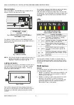
Page 6: ...bination thereof are possible See Excel 50 5000 LONWORKS Mechanisms EN0B 0270GE51 for details LEDs The EAGLE Controller features the following LEDs Fig 9 EAGLE Controller LEDs Table 4 EAGLE Controller LEDs symbol color function description L1 yellow application specific LED indicating status information Cooling Mode Heating Mode Service Interval etc L2 yellow Indicates connection of operationally ...

Page 7: ...llers not set to END or BIAS on bus should have this setting which is the default 47 kOHM 47 kOHM 5VISO GND 1 RS485 1 RS485 1 25 26 MID DEFAULT END BIAS MID Fig 11 RS485 1 three position slide switch setting MID 550 OHM 550 OHM 5VISO GND 1 RS485 1 RS485 1 25 26 BIAS END BIAS MID Fig 12 RS485 1 three position slide switch setting BIAS 550 OHM 150 OHM 550 OHM 5VISO GND 1 RS485 1 RS485 1 25 26 END EN...

Page 8: ...the laws of physics still require that a solid ground connection be provided for in order to ensure error free communication between drivers and receivers unless all of the devices are electrically isolated and no earth grounding exists IMPORTANT In the case of new EAGLE controller installations we strongly recommend using a separate signal ground wire Doing otherwise may possibly lead to unpredic...

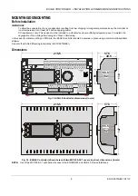
Page 9: ...roller should be secured in place using a commercially available stopper See also the EAGLE Mounting Instructions MU1Z 0970GE51 Dimensions 110 57 5 49 5 55 5 215 5 52 45 BI1 BI2 BI3 BI4 GND UI1 UI2 UI3 UI4 UI5 UI6 UI7 24 25 26 27 28 29 30 31 32 33 34 35 36 37 38 39 40 41 42 43 44 45 46 UI8 47 BO1 BO2 BO3 IN IN4 BO4 BO5 IN5 IN6 BO6 BO7 IN7 IN8 BO8 GND AO1 AO2 AO3 5 6 7 8 9 10 11 12 13 14 15 16 17 1...

Page 10: ...ept when the 3 position slide switch is set to END in which case the terminals of the RS485 1 bus 24 25 and 26 have no such protection Higher voltages may damage the device Do not open the controller housing Observe precautions for handling electrostatic sensitive devices NOTE All wiring must comply with applicable electrical codes and ordinances Refer to job or manu facturer s drawings for detail...

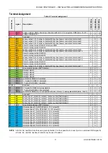
Page 11: ...ee NOTE below X X 20 AO1 Analog output 1 X X 21 AO2 Analog output 2 X X 22 AO3 Analog output 3 X 23 AO4 Analog output 4 X 24 GND 1 ref GND of RS485 1 isolated X X X 25 485 1 signal for RS485 1 isolated X X X 26 485 1 signal for RS485 1 isolated X X X 27 28 not used 29 485 2 signal for RS485 2 non isolated X X X 30 485 2 signal for RS485 2 non isolated X X X 31 GND 2 ref GND of RS485 2 int connecte...

Page 12: ...ng Panel Bus I O Modules and Field Devices The EAGLE Panel Bus I O modules and field devices can be powered by either separate transformers see Fig 19 Fig 20 and Fig 21 or by the same transformer see Fig 22 on pg 13 NOTE Use a min distance of 10 cm between power cables and 0 10 V sensor cables in order to prevent signal disturbances on the 0 10 V sensor cables See also section Cable Specifications...

Page 13: ...2 43 44 45 46 UI8 47 GND 37 DRY CONTACT 1 GND 2 SIGNAL 2 1 37 GND 37 GND 37 GND 37 GND 1 1 2 2 24V 1 GND 24V 0 2 24V POWER 3 0 10 VDC DRIVE with 0 10V SIGNAL 2 3 1 M 0 10 VDC NTC20kOHM SENSOR 1 GND 2 SIGNAL 1 2 NTC20kOHM SENSOR 1 GND 2 SIGNAL 1 2 24Vac ACTIVE SENSOR 1 GND 24V 0 2 24V POWER 3 0 10 VDC 2 3 1 24V 0 24V 1 2 L N BLOCK 1 BLOCK 2 WARNING Risk of electric shock or equipment damage Low vol...

Page 14: ... B7 1 2 3 4 5 6 7 A1 A2 A3 A4 A5 A6 A7 ACTIVE SENSOR 1 GND 24V 0 2 24V POWER 3 0 10 VDC 2 3 1 33 40 24V 0 24V 1 2 24Vac L N 2 1 BLOCK 1 BLOCK 2 BLOCK 1 BLOCK 2 DRY CONTACT 1 GND 2 SIGNAL 2 1 WARNING Risk of electric shock or equipment damage Low voltage and line voltage must not be wired within the same block Fig 23 CLEA2026Bxx connection example with two XS830 Auxiliary Terminal Packages The XS83...

Page 15: ...ing 24 VAC 200 k Vi GND Fig 24 Internal wiring of UI1 UI8 configured for voltage input without pull up resistor 200 k 25 k 10 VDC Vi GND Fig 25 Internal wiring of UI1 UI10 configured for input from NTC20kΩ or voltage input with pull up resistor Analog Outputs The CLEA2026Bxx is equipped with four CLEA2014Bxx two analog outputs AOs In the event of an application stop e g during application download...

Page 16: ...ged in two blocks BO1 4 and BO5 8 respectively WARNING Risk of electric shock or equipment damage Low voltage and line voltage must not be wired within the same block In the event of an application stop e g during application download the binary outputs assume the safety positions configured in CARE The polarity normal N O contact or reverse N C contact configuration defines if a relay is open or ...

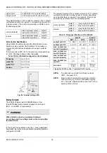
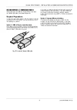
Page 17: ...ded interface for downloading applications and firmware via CARE An A Male to B Male USB cable is required Fig 27 A male to B male USB cable For access via USB the EAGLE Controller has a permanent default IP address 192 168 255 241 Your PC s IP address must match the EAGLE Controller s default IP address subnet We recommend using DHCP or Obtain an automatic IP address Option 2 Standard Ethernet In...

Page 18: ...1 package of 20 for EAGLE Controllers MVC 80 AC3 strain relief package of 10 for MVC 40x xxxxxx and MVC 80x xxxxxx Controllers A1 A2 A3 A4 A5 A6 A7 A8 A9 B1 B2 B3 B4 B5 B6 B7 B8 B9 XS830 Auxiliary Terminal Package for the Mixed Panel Bus I O Module and the EAGLE Controller only Please refer to CentraLine I O Modules Installation Commissioning Instructions EN1Z 0973GE51 for more information A1 B1 A...

Page 19: ...B9 9 3 B8 8 2 B7 7 1 DI Binary Inputs G1 G2 41 42 GND Analog Outputs AI2 AI3 AI4 14 15 16 AI1 17 18 19 20 13 Analog Inputs AO5 AO1 AO6 AO2 AO7 AO3 AO8 AO4 21 25 26 27 28 22 23 24 DO 24V Relays NO1 NO2 NO3 NO4 NO5 NO6 CO1 CO2 CO3 CO4 CO5 CO6 35 29 30 31 32 33 34 36 37 38 39 40 1 2 3 4 5 6 Install Instr MU1B 0473GE51 AI5 AI6 AI7 AI8 Honeywell CLIOP830A CLIOP830A w bridge connector or CLIOP831A w wir...

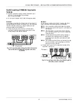
Page 20: ...24 0 CentraLine I O Module EAGLE F1 GND 1 GND 1 5VISO END END BIAS MID RS485 1 RS485 1 242526 230 V 24 V 550 OHM 550 OHM 150 OHM Fig 29 Connecting RS485 1 of the EAGLE with Panel Bus I O Modules single transformer 1 2 Com a 71 75 72 76 73 77 74 78 Com b 24V 24V 24 0 24 0 CentraLine I O Module Com a 71 75 72 76 73 77 74 78 Com b 24V 24 0 CentraLine I O Module Com a 71 75 72 76 73 77 74 78 Com b 24V...

Page 21: ...0 V 24 V GND 2 GND 2 5VISO RS485 2 RS485 2 550 OHM 550 OHM 130 OHM Fig 31 Connecting RS485 2 of the EAGLE with Panel Bus I O Modules single transformer 1 2 Com a 71 75 72 76 73 77 74 78 Com b 24V 24V 24 0 24 0 CentraLine I O Module Com a 71 75 72 76 73 77 74 78 Com b 24V 24 0 CentraLine I O Module Com a 71 75 72 76 73 77 74 78 Com b 24V 24 0 CentraLine I O Module Com a 71 75 72 76 73 77 74 78 Com ...

Page 22: ...e transformer 400 m Fig 20 sep transformers 24 VAC power 1 5 mm 2 16 AWG not allowed for 100 m 300 ft 0 10 V signals 0 081 2 08 mm 2 28 14 AWG For wiring field devices see section Powering Panel Bus I O Modules and Field Devices on page 12 Routing Cables to Field Devices Route low voltage signal and output cables to field devices separately from mains cables Table 20 Minimum distances to power mai...

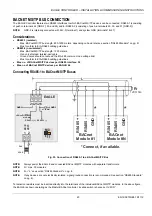
Page 23: ...age limit Must conform to EIA RS485 cabling guidelines Max no of BACnet MS TP devices per RS485 interface 32 Max no of BACnet MS TP devices per EAGLE 64 Connecting RS485 1 to BACnet MS TP Buses 1 2 24V 24 0 EAGLE MID END BIAS MID 242526 RT BACnet Module 1 RS485 RS485 GND BACnet Module N Connect if available 120 Ohm RS485 RS485 GND F1 230 V 24 V L GND 1 GND 1 5VISO RS485 1 RS485 1 47 kOHM 47 kOHM F...

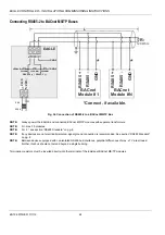
Page 24: ...Bus NOTE Always power the EAGLE and connected BACnet MS TP modules with separate transformers NOTE N max 30 modules NOTE For L see section RS485 Standard on pg 8 NOTE If any devices are not electrically isolated signal ground connection is recommended See section RS485 Standard on pg 8 NOTE Between devices equipped with non isolated RS485 bus interfaces potential differences of max 7 V are allowed...

Page 25: ...m persists check and if necessary reload the application If problem still persists replace hardware Tx and Rx LEDs Table 23 EAGLE Controller bus LEDs Tx and Rx case bus LEDs meaning remedy 1 Both Tx and Rx are flashing Normal operation the isolated BACnet MS TP Bus is functioning properly No action necessary 2 Both Tx and Rx are OFF No communication on the isolated BACnet MS TP Bus Switch ON commu...

Page 26: ...controlled electrical device EN60204 1 requires controllers to be powered by PELV Protective Extra Low Voltage and earth grounding of the secondary side of the used transformers or earth grounding of the system ground Earth grounding is prescribed to prevent unexpected start up of connected rotating moving machines due to an insulation fault and double earth grounding somewhere in the plant In ord...

Page 27: ...nd its Panel Bus I O Modules together with other controllers Example 2 Connecting and earthing the EAGLE together with other mixed controllers earth grounded as per EN60204 1 NOTE Use a noise free earth ground inside the cabinet NOTE Use one star point to split power for controllers and field devices NOTE If the transformer is used for several controllers each controller ground has to be wired sep...

Page 28: ...sor Failure of Sensor Inputs The thresholds at which sensor failures i e sensor breaks SB and short circuits SC are recognized depends upon the given sensor type In the event of a recognized sensor failure the sensor inputs assume the safety values configured in CARE Table 25 lists the measurement ranges and the corresponding thresholds for the recognition of sensor failure for the various differe...

Page 29: ... 8 26 2 42 46 0 7 92 2 34 47 0 7 60 2 27 48 0 7 29 2 20 49 0 7 00 2 14 Temp C Resistance k Terminal voltage V 50 0 6 72 2 07 51 0 6 45 2 01 52 0 6 19 1 94 53 0 5 95 1 88 54 0 5 72 1 82 55 0 5 49 1 77 56 0 5 28 1 71 57 0 5 08 1 66 58 0 4 88 1 61 59 0 4 69 1 56 60 0 4 52 1 51 61 0 4 35 1 46 62 0 4 18 1 41 63 0 4 03 1 37 64 0 3 88 1 32 65 0 3 73 1 28 66 0 3 59 1 24 67 0 3 46 1 20 68 0 3 34 1 16 69 0 ...

Page 30: ...MVC 80 AC2 front door mounting accessory 18 TPU 11 01 removable push in terminal plugs 10 18 TPU 45 01 removable push in terminal plugs 10 18 XS830 Auxiliary Terminal Package 14 18 XS831 Auxiliary Terminal Package 14 18 fusing 10 LEDs 5 BACnet MS TP LED troubleshooting 6 25 L1 3 6 L2 3 6 power LED 3 6 troubleshooting 25 status LED 3 6 troubleshooting 25 USB A LED 3 Panel Bus connection 19 multiple...

Reviews: