background image

EAGLEHAWK NX CONTROLLER – INSTALLATION & COMMISSIONING INSTRUCTIONS 


35 

EN1Z-1039GE51 R1218 


Addressing Panel Bus I/O Modules 

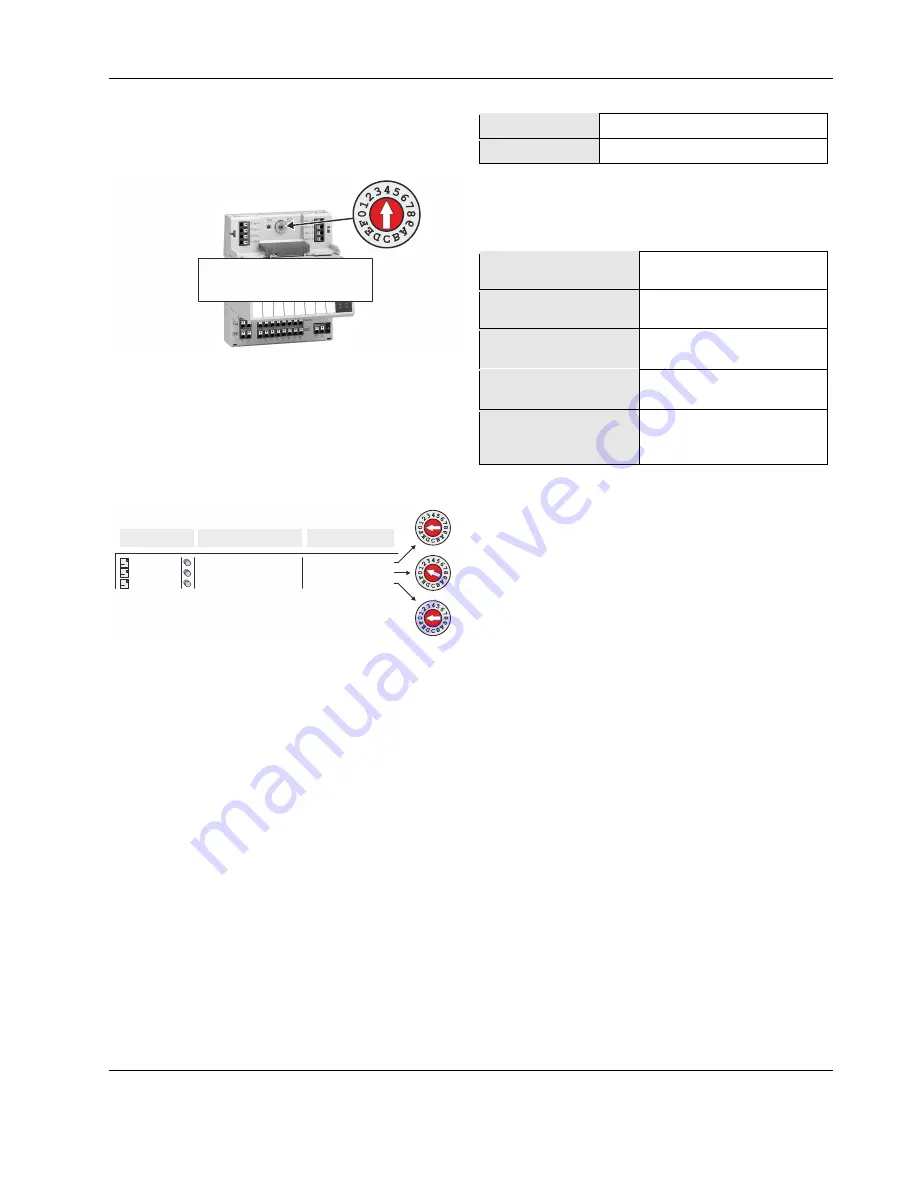
Each Panel Bus I/O Module must be addressed manually 
using its HEX switch (S2). The HEX switch setting is defined 
using the COACH NX engineering tool. 

PANEL BUS I/O MODULE

(EXAMPLE)


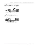
Fig. 38. Location of HEX switch on Panel Bus I/O Module 

NOTE:

  A HEX switch setting of "0" corresponds to an 

address in COACH NX of "1," a setting of "1" cor-
responds to an address of "2," and so on. 

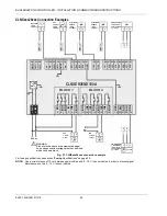
During commissioning, a max. of 16 Panel Bus I/O Modules 
of each type (AI, DO, etc.) can be assigned addresses. In 
doing so, no two modules of the same type (e.g., no two 
Analog Input Modules, no two Digital Output modules, etc.) 
may be assigned the same address. See also Fig. 39. 

CLIOP831_A1

01 (addr.Switch = 0)

01 (addr.Switch = 0)

02 (addr.Switch = 1)

CLIOP831_A2
CLIOP824_A8

NAME

ADDRESS

MODEL

CLIOP830/831 (Mixed...)
CLIOP824 (Relay...)


Fig. 39. HEX switch setting and corresponding address 

Failing to observe this requirement will cause a "Fail [date] 
timeout" error message to appear in the "Health" column, and 
the device status "down" to appear in the "Status" column. 
This same error message will likewise appear if an address is 
assigned to a module with which the controller cannot, for any 
reason (e.g., due to defective wiring, or because the module 
has not been physically installed, etc.), communicate. 
 

Automatic Updating of Panel Bus I/O Module 

Firmware 

The firmware of the Panel Bus I/O modules is part of the 
EAGLEHAWK NX firmware. The EAGLEHAWK NX controller 
will thus automatically update the firmware of the Panel Bus 
I/O modules as soon as it detects an older version in them. 
 

Cable Specifications 

Panel Bus I/O Modules 

When checking the length of the power supply cable, the 
connection cables to all Panel Bus I/O Modules must be 
taken into account. 

Table 20. Power supply cable specifications 

max. length 

3 m (from transformer to final module) 

cross section 

min. 0.75 mm

(AWG 18) 


EIA 485 Cable Specifications 

The following cable specification is valid for all EIA 485 buses 
(e.g., Panel Bus, Modbus, and BACnet MS/TP). 

Table 21. EIA 485 cable specifications 

max. length 

1200 meters (9.6 – 78.8 kbps) 

or 800 meters (115.2 kbps). 

cable type 

twisted pair, shielded (foil or 

braided shields are acceptable) 

characteristic 
impedance 

100…130 Ω 

distributed capacitance 
between conductors 

Less than 100 pF per meter 

(30 pF per foot) 

distributed capacitance 
between conductors and 
shield 

Less than 200 pF per meter 

(60 pF per foot) 

 
The following cables fulfill this requirement: 
•  AWG 18; 
•  shielded, twisted pair cable J-Y-(St)-Y 2 x 2 x 0,8; 
•  CAT 5,6,7 cable (use only one single pair for one bus); 
•  Belden 9842 or 9842NH. 
 

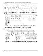
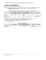
Summary of Contents for CENTRA LINE EAGLEHAWK NX

Page 1: ...ce to a Panel Bus 33 Connecting EAGLEHAWK NX via its RS485 2 Interface to a Panel Bus 34 Addressing Panel Bus I O Modules 35 Automatic Updating of Panel Bus I O Module Firmware 35 Cable Specifications 35 Tuning Panel Bus Communication 36 Field Devices 38 LonWorks Communications 39 General Information 39 Connecting to a LONWORKS Network 39 BACnet MS TP Bus Connection 40 BACnet MS TP Bus Considerati...

Page 2: ... per EN 60730 Purpose The purpose of the device is OPERATING CONTROL The EAGLEHAWK NX controller is a multifunctional non safety control device intended for HVAC in home residential commercial and light industrial environments Construction The EAGLEHAWK NX controller is an independently mounted electronic control unit with fixed wiring Mounting Method The EAGLEHAWK NX controller is suitable for mo...

Page 3: ...ion Max 9 W at DC power supply max 9 W at AC power supply Current consumption typically DC 300 mA max 375 mA typically AC 400 mA max 500 mA Ambient temperature 0 40 C wall mounting 0 50 C cabinet door mounting Storage temperature 20 70 C Humidity 5 95 r h non condensing Dimensions See Fig 20 and Fig 21 Degree of protection IP20 mounted on walls with two accessory MVC 80 AC1 covers IP30 mounted in ...

Page 4: ...lated BACnet MS TP Panel Bus or Modbus RTU Master or Slave communication NOTE It is imperative that the RS485 2 be powered by a power supply having the proper polarity Failure to do so will make data transmission impossible 1 1200 m 1 2 1 1 2 1 1 2 1 1 2 1 1 2 1 1 2 1 Ethernet Interfaces e mail communication browser access BACnet IP communication Niagara Network Modbus TCP 100 m 2 2 2 2 2 2 2 2 2 ...

Page 5: ...NWORKS systems including CentraLine LONWORKS I O Modules Auxiliary parts see section Extra Parts on page 30 enable special features ARENA NX HAWK 8000 LYNX LYNX LYNX LIGHTING SHADING TEMP MERLIN LIGHTING FIRE SECURITY VIDEO HOTEL RESERVATIONS PANTHER TIGER LION EXCEL 5000 ARENA NX ENERGY EAGLEHAWK NX SERVAL EASY CLICK MOBILE EAGLE SUPERVISION AND ENERGY MANAGEMENT INTEGRATION AND HVAC PLANT CONTRO...

Page 6: ... 31 32 5 6 GND1 485 1 485 1 n a n a GND2 485 2 485 2 n a 1 2 3 4 RS232 RS485 1 END BIAS MID BI1 BI2 BI3 BI4 GND UI1 UI2 UI3 UI4 UI5 UI6 UI7 33 34 35 36 37 38 39 40 41 42 43 44 45 46 UI8 47 UI9 UI10 2 1 Fig 2 Top view with HMI and full complement of onboard I Os 1 2 END BIAS MID 4 3 Fig 3 Side view Legend 1 RS232 RJ45 socket for connection of M Bus and other RS232 based protocols factory debugging ...

Page 7: ...200 mA high speed See also section LonWorks Communications on pg 39 END BIAS MID USB 2 0 HOST INTERFACE Fig 6 USB 2 0 Host interface USB 2 0 Device Interface All models of the EAGLEHAWK NX controller are equipped with a USB 2 0 Device Interface at the front This interface is for connection to COACH NX and web browsers or 3rd party touch panels USB 2 0 DEVICE INTERFACE Fig 7 USB 2 0 Device Interfac...

Page 8: ...enabled Ethernet Inter face In Fig 10 the gateway address is 192 168 1 1 hence the IP address of Ethernet adapter 1 must be in the range of 192 168 1 2 to 192 168 1 255 Default IP Addresses of Ethernet Interfaces 1 and 2 In any case the default IP address of Ethernet interface 1 is 192 168 200 20 mask 255 255 255 0 and the default IP address of Ethernet interface 2 is 192 168 201 20 mask 255 255 2...

Page 9: ...mall bus networks a min of one and a max of two controllers should have this setting MID All other controllers not set to END or BIAS on bus should have this setting which is the default 47 kOHM 47 kOHM 5VISO GND 1 RS485 1 RS485 1 25 26 MID DEFAULT END BIAS MID Fig 14 RS485 1 three position slide switch setting MID 550 OHM 550 OHM 5VISO GND 1 RS485 1 RS485 1 25 26 BIAS END BIAS MID Fig 15 RS485 1 ...

Page 10: ...possibly lead to unpredictable behavior if other electrically non isolated devices are connected and the potential difference is too high In the case of the installation of EAGLEHAWK NX controllers in already existent RS485 two wire systems e g when replacing PANTHER and LION controllers with EAGLEHAWK NX controllers not using a separate signal ground wire will probably have no undesirable effects...

Page 11: ...ifications Modbus Compliance As per the Modbus standard the EAGLEHAWK NX controller is a conditionally compliant regular Modbus device The EAGLEHAWK NX controller differs from an uncon ditionally compliant regular Modbus device in that it does not support communication rates of 1 2 2 4 and 4 8 kbps because these communication rates are not market relevant Physical Layer 2 wire serial line RS485 EI...

Page 12: ...factory defaults see step 7 below Before proceeding see section Procedure below you must first connect the RS232 interface of the EAGLEHAWK NX controller and the PC on which PuTTY is running using the following two cables connected end to end XW586 and XW585 The interface parameters for serial communication are as shown in the following screenshot Procedure 1 Start PuTTY As soon as the following l...

Page 13: ...lts press F in the Boot menu ATTENTION Resetting the controller to its factory defaults will result in the following The station will be deleted The platform credentials will be deleted The IP settings will be reset to the factory defaults see section Default IP Addresses of Ethernet Interfaces 1 and 2 on pg 8 RECOMMENDATION Before leaving closing the terminal program go to Network Setup and enter...

Page 14: ...ws http standard port 80 to 8080 https standard port 443 to 8443 After the changes are done the controller is reachable via both pairs of ports i e via the old standard ports and via the newly set ports Procedure 1 In the COACH NX Nav tree expand the Services folder and then double click WebService RESULT The Property Sheet Sheet displays to the right 2 Expand the Http Port and Https Port options ...

Page 15: ... Platform Administration and check the version of the Niagara Runtime installed in the EAGLEHAWK NX 2 Close COACH NX 3 Get the firmware upgrade package from the CentraLine Partnerweb At present this package is contained in EAGLEHAWKNX SupportPackage_17July2018 zip 4 Navigate with Windows Explorer to your installation folder For version NX 4 4 73 24 the default folder is c CentraLine CentraLineNX 4...

Page 16: ...Home link you will be redirected to the user home 6 Navigate to user home sw inbox folder Resulting path for 4 4 is C Users your username Niagara4 4 tridium sw inbox 7 Copy and paste all four firmware files contained in the firmware upgrade package into the aforementioned inbox 8 Run the platform daemon 9 Restart COACH NX ...

Page 17: ...ATION COMMISSIONING INSTRUCTIONS 17 EN1Z 1039GE51 R1218 10 Connect to the EAGLEHAWK NX and start the Commissioning Wizard 11 Deactivate all checkboxes only Update Core Software needs to be selected 12 Start the commissioning process ...

Page 18: ...K NX CONTROLLER INSTALLATION COMMISSIONING INSTRUCTIONS EN1Z 1039GE51 R1218 18 13 After a successful update the Platform Administration should show the new firmware version in the Niagara Runtime field FINISHED ...

Page 19: ...vailable stopper See also the EAGLEHAWK NX Mounting Instructions MU1Z 1039GE51 Dimensions 110 215 5 52 45 24V 0 24V 1 2 49 5 57 5 J1 J8 24 25 26 27 28 29 30 31 32 GND1 485 1 485 1 n a n a GND2 485 2 485 2 n a RS232 RS485 1 END BIAS MID BI1 BI2 BI3 BI4 GND UI1 UI2 UI3 UI4 UI5 UI6 UI7 33 34 35 36 37 38 39 40 41 42 43 44 45 46 UI8 47 UI9 UI10 2 1 DO1 DO2 DO3 IN IN4 DO4 DO5 IN5 IN6 DO6 DO7 IN7 IN8 DO8...

Page 20: ...wired to it Do not use spare terminals as wiring support points To prevent risk of injury due to electrical shock and or damage to the device due to short circuiting low voltage and high voltage lines must be kept separate from one another All terminals are protected up to 24 VAC against short circuiting and incorrect wiring unless the 3 position slide switch is set to END in which case the termin...

Page 21: ...og output 2 X X 22 AO3 Analog output 3 X 23 AO4 Analog output 4 X 24 GND 1 ref GND of RS485 1 isolated X X X 25 485 1 signal for RS485 1 isolated X X X 26 485 1 signal for RS485 1 isolated X X X 27 28 not used 29 485 2 signal for RS485 2 non isolated X X X 30 485 2 signal for RS485 2 non isolated X X X 31 GND 2 ref GND of RS485 2 int conn with 24V 0 term 1 and system GND term 19 37 X X X 32 not us...

Page 22: ... 6 In the U S and Canada if the EAGLEHAWK NX is powered by transformers then such transformers must be NEC Class 2 transformers Table 9 1450 series transformers data part 1450 7287 primary side secondary side 001 120 VAC 24 VAC 50 VA 002 120 VAC 2 x 24 VAC 40 VA 100 VA from separate transformer 003 120 VAC 24 VAC 100 VA 24 VDC 600 mA 004 240 220 VAC 24 VAC 50 VA 005 240 220 VAC 2 x 24 VAC 40 VA 10...

Page 23: ...output module max 400 m CLIOP822A 73 74 1 8 GND Y 24 VAC 11 18 24 V0 230 VAC 24 VAC F2 Y 0 10 Vdc 24 V0 230 VAC 24 VAC F1 Fig 25 Power supply via a separate transformer Powering Field Devices via Panel Bus I O Module 24 V actuator connected to e g an analog output module Field device located max 100 m from the analog output module Y 0 10 Vdc 24 V0 230 VAC 24 VAC max 100 m CLIOP822A 73 74 1 8 GND Y...

Page 24: ... 41 42 43 44 45 46 UI8 47 GND 37 DRY CONTACT 1 GND 2 SIGNAL 2 1 37 GND 37 GND 37 GND 37 GND 1 1 2 2 24V 1 GND 24V 0 2 24V POWER 3 0 10 VDC DRIVE with 0 10V SIGNAL 2 3 1 M 0 10 VDC NTC20kOHM SENSOR 1 GND 2 SIGNAL 1 2 NTC20kOHM SENSOR 1 GND 2 SIGNAL 1 2 24Vac ACTIVE SENSOR 1 GND 24V 0 2 24V POWER 3 0 10 VDC 2 3 1 24V 0 24V 1 2 L N BLOCK 1 BLOCK 2 WARNING Risk of electric shock or equipment damage Lo...

Page 25: ...6 7 A1 A2 A3 A4 A5 A6 A7 ACTIVE SENSOR 1 GND 24V 0 2 24V POWER 3 0 10 VDC 2 3 1 33 40 24V 0 24V 1 2 24Vac L N 2 1 BLOCK 1 BLOCK 2 BLOCK 1 BLOCK 2 DRY CONTACT 1 GND 2 SIGNAL 2 1 WARNING Risk of electric shock or equipment damage Low voltage and line voltage must not be wired within the same block CLNXEH26ND100A Fig 28 CLNXxxx26xxx connection example with two XS830 Auxiliary Terminal Packages The XS...

Page 26: ...es NTC10kΩ 30 100 C NTC20kΩ 50 150 C Slow binary input static dry contact 0 4 Hz resolution 12 bit resolution accuracy 75 mV 0 10 V protection against short circuiting 24 VAC 200 k Vi GND Fig 29 Internal wiring of UI1 UI8 configured for voltage input without pull up resistor 200 k 25 k 10 VDC Vi GND Fig 30 Internal wiring of UI1 UI10 configured for input from NTC10kΩ NTC20kΩ voltage input with pul...

Page 27: ...C protection against short circuiting 24 VAC Binary Input Specifications The binary inputs of the EAGLEHAWK NX are static dry contact inputs This reduces the wiring effort as it is then not necessary to distribute an auxiliary voltage signal open contact 3000 Ω 24 VDC on BI terminal closed contact 500 Ω short circuit current 2 0 mA The polarity normal N O contact or reverse N C contact configurati...

Page 28: ... selecting in COACH NX one of the following options normal default state 1 relay contact is closed state 0 relay contact is opened reverse state 0 relay contact is closed state 1 relay contact is opened Table 16 Relay specifications of the EAGLEHAWK NX block 1 block 2 BO1 3 BO4 BO5 8 contact volt AC 5 253 V 5 253 V 5 253 V contact volt DC 5 30 V 20 30 V 5 30 V max contact cur rent AC resistive 3 A...

Page 29: ...2 168 200 20 and the default IP address of Ethernet interface 2 is 192 168 201 20 In any case your PC s IP address must match the EAGLEHAWK NX controller s default IP address subnet 255 255 255 0 Behavior of Outputs during Download Table 17 Behavior of outputs during firmware download application download analog binary and floating outputs output behavior during firmware download output behavior d...

Page 30: ...rminals Each package consists of two groups of four pairs of push in terminals each with a 499 Ω resistor for converting 0 20 mA signals into 0 10 VDC signals and one push in ground terminal per group TPU 11 01 Removable terminal plugs push in type complete set of 3 plugs for terminals 1 2 24 32 for the CLNXxxx00xxx TPU 45 01 Removable terminal plugs push in type complete set of 9 plugs for termin...

Page 31: ...ts 1st year of Software Maintenance Agreement CLNXEH14D100A CLNXEH26D100A CLNXEHS00D100A 100 integration points Onboard I O points CLNXEHS14D100A CLNXEHS26D100A CLNXEHSERIES00D N A CLNXEHSERIES14D N A CLNXEHSERIES26D N A CLNXEHPB100UP 102 Panel Bus onboard I O points upgrade CLNXEHPB255UP 255 Panel Bus onboard I O points upgrade CLNXEHRBAC250UP 250 Honeywell BACnet points for BACnet room devices e...

Page 32: ...LIOP830A CLIOP831A CLIOP831A Fig 33 Overview of Panel Bus I O Modules Panel Bus Considerations RS485 1 isolated Max Panel Bus length o 40 meters Any type of cabling and topology including star and loop topology possible No additional end termination permitted o 1200 meters 9 6 78 8 kbps or 800 meters 115 2 kbps see also section RS485 Standard on pg 10 Mandatory twisted pair or telephone cable and ...

Page 33: ...Module F1 GND 1 GND 1 5VISO END END BIAS MID RS485 1 RS485 1 242526 230 V 24 V 550 OHM 550 OHM 150 OHM RT 120 Ohm EAGLE HAWK NX Fig 34 Connecting an EAGLEHAWK NX controller via its RS485 1 interface to a Panel Bus single transformer 1 2 Com a 71 75 72 76 73 77 74 78 Com b 24V 24V 24 0 24 0 CentraLine I O Module Com a 71 75 72 76 73 77 74 78 Com b 24V 24 0 CentraLine I O Module Com a 71 75 72 76 73...

Page 34: ...30 OHM RT 120 Ohm END BIAS MID NO EFFECT ON RS485 2 EAGLE HAWK NX Fig 36 Connecting an EAGLEHAWK NX controller via its RS485 2 interface to a Panel Bus single transformer 1 2 Com a 71 75 72 76 73 77 74 78 Com b 24V 24V 24 0 24 0 CentraLine I O Module Com a 71 75 72 76 73 77 74 78 Com b 24V 24 0 CentraLine I O Module Com a 71 75 72 76 73 77 74 78 Com b 24V 24 0 CentraLine I O Module Com a 71 75 72 ...

Page 35: ...which the controller cannot for any reason e g due to defective wiring or because the module has not been physically installed etc communicate Automatic Updating of Panel Bus I O Module Firmware The firmware of the Panel Bus I O modules is part of the EAGLEHAWK NX firmware The EAGLEHAWK NX controller will thus automatically update the firmware of the Panel Bus I O modules as soon as it detects an ...

Page 36: ... updated every 10s Write commands are sent without time delay It is recommended that you update the polling interval of those points requiring more frequent updating see Fig 40 IMPORTANT For EAGLEHAWK NX the fastest poll rate is 200 milliseconds Do NOT set a faster poll rate as this may overload the CPU in larger systems Fig 40 Editing the standard polling interval in Poll Scheduler of Property Sh...

Page 37: ... INSTRUCTIONS 37 EN1Z 1039GE51 R1218 You can assign different poll intervals to individual points in the Panel Bus Point Discovery Dialog see Fig 41 Fig 41 Assigning different poll intervals to individual points in the Panel Bus Point Discovery Dialog ...

Page 38: ...Modules and Field Devices on page 22 Routing Cables to Field Devices Route low voltage signal and output cables to field devices separately from mains cables Table 23 Minimum distances to power mains cables cable min distance shielded 10 mm 0 4 in unshielded 100 mm 4 in All low voltage signal and output cables should be regarded as communication circuits in accordance with VDE 0100 and VDE 0800 or...

Page 39: ...number 9H2201504 non shielded twisted pair solid conductor wire When possible use Honeywell AK3781 AK3782 AK3791 or AK3792 cable US part numbers See Excel 50 5000 LONWORKS Mechanisms EN0B 0270GE51 for details including maximum lengths Use wire with a minimum size of 20 AWG 0 5 mm2 and a maximum size of 14 AWG 2 5 mm2 IF LON2 Optionally communication with physical I O modules with room and zone con...

Page 40: ...limit Must conform to EIA RS485 cabling guidelines Should not extend beyond a single building Connecting EAGLEHAWK NX via its RS485 1 Interface to a BACnet MS TP Bus With regards to Fig 44 through Fig 46 please note the following NOTE Always power each EAGLEHAWK NX controller and the connected BACnet MS TP modules via separate transformers NOTE For L see section RS485 Standard on pg 10 NOTE If any...

Page 41: ...o a BACnet MS TP Bus Example 3 Multiple EAGLEHAWK NX Controllers and Connected BACnet Modules with inserted termination resistor 1 1 1 1 2 2 2 2 24V 24V 24V 24V 24 0 24 0 24 0 24 0 24 24 25 25 26 26 RS485 RS485 GND BACnet Module RS485 RS485 GND F1 F1 F1 F1 230 V 230 V 230 V 230 V 24 V 24 V 24 V 24 V L GND 1 GND 1 5VISO 5VISO RS485 1 RS485 1 RS485 1 RS485 1 47 kOHM 47 kOHM END END BIAS MID END BIAS...

Page 42: ...5 RS485 RS485 RS485 RS485 RS485 RS485 RS485 GND GND GND GND L BACnet Module 1 END BIAS MID NO EFFECT ON RS485 2 CONNECT GND IF AVAILABLE 120 OHM EAGLE HAWK NX Fig 47 Connection of a single EAGLEHAWK NX controller via its RS485 2 interface to a BACnet MS TP Bus The termination resistor must be inserted directly into the terminals of the last BACnet MS TP module Example 2 Multiple EAGLEHAWK NX Contr...

Page 43: ...s or 800 meters 115 2 kbps see also section RS485 Standard on pg 10 Use only shielded twisted pair cable and daisy chain topology Must conform to EIA RS485 cabling guidelines see section EIA 485 Cable Specifications on pg 35 RS485 2 non isolated Max Modbus length 1200 meters 9 6 78 8 kbps or 800 meters 115 2 kbps see also section RS485 Standard on pg 10 Use only shielded twisted pair cable and dai...

Page 44: ...MID Modbus Module 1 Modbus Module 2 RS485 RS485 GND Modbus Module 3 Modbus Module 4 Modbus Module N 1 Modbus Module N RS485 RS485 RS485 RS485 RS485 GND GND GND RT RS485 RS485 RS485 GND CONNECT GND IF AVAILABLE 120 OHM EAGLE HAWK NX Fig 49 Connection of an EAGLEHAWK NX Modbus master controller via its RS485 1 interface to a Modbus with slaves The termination resistor must be inserted directly into ...

Page 45: ... Modbus Master Controller and Connected Modbus Slaves with inserted termination resistor 1 2 24V 24 0 293031 GND 2 GND 2 5V RS485 2 RS485 2 550 OHM 550 OHM 130 OHM F1 230 V 24 V RT Modbus Module 2 RS485 RS485 GND Modbus Module 3 Modbus Module 4 Modbus Module N 1 Modbus Module N RS485 RS485 RS485 RS485 RS485 RS485 RS485 RS485 GND GND GND GND L Modbus Module 1 END BIAS MID NO EFFECT ON RS485 2 CONNE...

Page 46: ...le 25 In case a third party cable is used instead of the XW586 cable the third party cable must have a max length of 15 meters and a max cable capacitance of 2 500 pF Table 24 EAGLEHAWK NX RS232 RJ45 socket specifications RJ45 plug pin no RS232 function 1 2 RxD 3 TxD 4 5 GND 6 7 8 8 7 654 3 21 Fig 52 EAGLEHAWK NX RS232 RJ45 socket Table 25 RS232 to PW cable specifications RJ45 plug pin no RS232 fu...

Page 47: ...e END BIAS MID XW586 EAGLEHAWK NX M BUS DEVICE RS232 RJ45 SOCKET Fig 56 Connecting the EAGLEHAWK NX to the PW M Bus adapter 4 Connect 24 V power to the M Bus Adapter WARNING Risk of electric shock or equipment damage Due to the risk of short circuiting see Fig 23 it is strongly recommended that the EAGLEHAWK NX controller be supplied with power from a dedicated transformer However if the EAGLEHAWK...

Page 48: ...no of hardware I O points points in PX pages freq of value changes histories enabled CPU usage test result Panel Bus via RS485 1 46 A 491 491 B 2 sec poll rate 30 occasionally 50 OK for non critical applications C BACnet MS TP via RS485 2 13 559 559 D 2 sec COV 500 A 9x CLIOP821A 9x CLIOPR822A 9x CLIOP823A 9x CLIOPR824 5x CLIOPR825 5x CLIOP830A B Four 4 PX pages AI AO BI and BO points each in a de...

Page 49: ...Check wiring If problem persists replace hardware Status LED red of EAGLEHAWK NX Table 29 EAGLEHAWK NX controller status LED case status LED meaning remedy 1 OFF after power up Normal operation No action necessary 2 ON con tinuously after power up Indicates an active alarm is controlled by Niagara Alarm System is configurable Try powering down and then powering up the EAGLEHAWK NX controller If pr...

Page 50: ...Rx are OFF No communication on RS485 1 Switch ON communication on RS485 1 L1 should then flash Further handling like case 4 below 3 Rx is flashing and Tx is OFF Communication on RS485 1 has been switched OFF but the EAGLEHAWK NX is receiving data from other controllers Switch ON communication on RS485 1 If this proves unsuccessful the hardware may be defective 4 Tx is flashing and Rx is OFF The EA...

Page 51: ...s not mandatory this is because electrical safety is provided by the use of SELV and transformers according to standard EN60742 Safety against unexpected start up of rotating moving machines If the application plant does not contain machines that can be harmful to the operator due to an unexpected start up the standard EN60204 1 is not applicable If such machines are encountered then EN60204 1 mus...

Page 52: ...hich is usually terminal 1 24V 0 and terminal 2 24V In the following example CPU 3 has a deviating numbering and must be connected accordingly NOTE When using a single transformer for several CPUs each CPU ground must be wired separately to the star point NOTE If the field device transformer is physically far away from the CPUs earth grounding must still be performed for the controller NOTE Use on...

Page 53: ...e g a connected Panel I O module Recognition of Sensor Failure of Sensor Inputs The thresholds at which sensor failures i e sensor breaks SB and short circuits SC are recognized depends upon the given sensor type In the event of a recognized sensor failure the sensor inputs assume the safety values configured in COACH NX Table 34 lists the measurement ranges and the corresponding thresholds for th...

Page 54: ...7 44 0 8 61 2 49 45 0 8 26 2 42 46 0 7 92 2 34 47 0 7 60 2 27 48 0 7 29 2 20 49 0 7 00 2 14 50 0 6 72 2 07 51 0 6 45 2 01 52 0 6 19 1 94 53 0 5 95 1 88 54 0 5 72 1 82 55 0 5 49 1 77 56 0 5 28 1 71 57 0 5 08 1 66 58 0 4 88 1 61 59 0 4 69 1 56 60 0 4 52 1 51 61 0 4 35 1 46 Temp C Resistance k Terminal voltage V 62 0 4 18 1 41 63 0 4 03 1 37 64 0 3 88 1 32 65 0 3 73 1 28 66 0 3 59 1 24 67 0 3 46 1 20...

Page 55: ... 115 22 11 418 3 025 23 10 921 2 937 24 10 449 2 850 25 10 2 767 26 9 572 2 684 27 9 165 2 603 28 8 777 2 524 29 8 408 2 447 30 8 057 2 372 31 7 722 2 299 32 7 402 2 228 33 7 098 2 159 34 6 808 2 091 35 6 531 2 025 36 6 267 1 962 37 6 015 1 900 38 5 775 1 840 39 5 546 1 781 40 5 327 1 724 41 5 117 1 669 42 4 917 1 616 43 4 726 1 564 44 4 543 1 514 45 4 369 1 465 46 4 202 1 418 47 4 042 1 373 48 3 ...

Page 56: ...onsumption 3 extra parts TPU 11 01 removable push in terminal plugs 20 TPU 45 01 removable push in terminal plugs 20 fusing 20 LEDs 6 L1 8 45 L2 8 46 power LED 8 45 Rx 8 46 status LED 8 45 Tx 8 46 M Bus connection 42 Modbus connection 10 39 via RS485 1 8 40 via RS485 2 8 41 Panel Bus connection 30 multiple rails single transformer 31 32 via RS485 1 8 via RS485 2 8 power supply failure indication 4...

Reviews: