TITLE
Model
DOCUMENT NO.
PAGE
CK75 Repair Manual
CK75
L3-GLBL-RPR-4254
(Rev A)
Page
30
of
42
2.
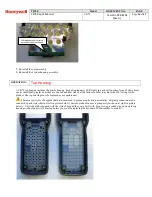
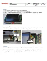
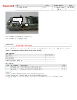
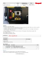
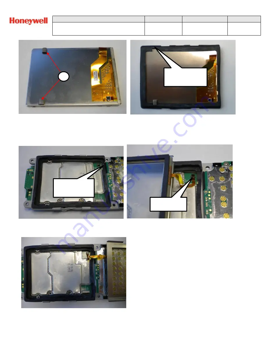
Position the boot in the magnesium frame. Make sure it is oriented correctly with the cutout for the touch panel flex located
down by the keyboard PCB.
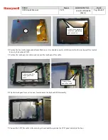
3.
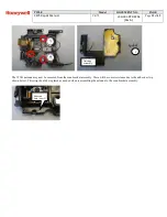
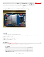
Position the touch panel as shown and connect the touch panel flex cable.
4.
Flip the touch panel over so it is now located above the keyboard PCB assembly.
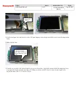
5.
Connect the LCD flex cable to the main logic board and then position the LCD panel down into the boot.
Use boot as a guide to
install new grounding
pads as needed
4
Cutout in boot for
touch panel flex
cable
Connect touch
panel flex cable

