background image


INSTALLATION 

To avoid personal injury (electrical shock) and to 
prevent equipment damage, before installation, you 
must remove power. 


These actuators are designed for single-point mounting. 

Mounting Instructions 

All information and steps are included in the Installation 
Instructions supplied with each actuator. 

Mounting Position 

The actuators can be mounted in any position (IP54 is dependent 
upon orientation; see Fig. 5). Choose a mounting pKosition 
permitting easy access to cables and controls. 


Fig. 5.   Mounting for IP54 

NOTE:   Further, in order to guarantee IP54, only original 

Honeywell grommets may be used. 

Anti-Rotation Bracket and Screws 

If the actuator is to be mounted directly on a damper shaft, use 
the anti-rotation bracket and screws included in the delivery 
package. The min. distance between the center of the damper 
shaft and the middle of the anti-rotation bracket is 3.35 in.; a 
max. of 4.25 in. is allowed (see also Fig 11). 

Depending upon the specifics of your mounting site, the actuator 
may shift in position slightly while tightening the screws at the top 
of the shaft adapter. The anti-rotation bracket features a T-piece 
with a 5-mm-long shank to accommodate for this movement. It is 
important to ensure that this play is not impeded. 

Universal Shaft Adapter 

The universal shaft adapter can be used for shafts of various 
diameters and shapes (round: 3/8...5/8 in. and square:           
1/4...1/2 in.). 


WIRING 


To avoid personal injury (electrical shock) and to 
prevent equipment damage, before wiring, you  
must remove power. 

Access Cover 

IMPORTANT 

Once the access cover has been removed, please 
 take care to avoid damaging any of the parts now 
accessible. 

 The access cover can be unscrewed and removed in order to 
gain access to the terminal block(s) and perform wiring. 


Fig. 6.   Access Cover 

Wiring Diagrams 


Fig. 7.   CN6105/CN6110 (floating mode) 


CN0B-0544CH33 R0805B 

CN05,CN10 SERIES DAMPER ACTUATORS FOR FLOATING/2-POSITON CONTROL 

Summary of Contents for CN05 Series

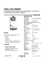
Page 1: ... All values stated hereinafter apply to operation under nominal voltage conditions Power consumption CN6105 CN6110 5 VA 2 W CN4605 22 VA 2 W at 50 Hz CN4610 25 VA 2 W at 60 Hz Ambient limits Ambient operating limits 5 140 F 20 60 C Ambient storage limits 22 176 F 30 80 C Relative humidity 5 95 non condensing Safety Protection standard IP54 Protection class II as per EN 60730 1 Overvoltage category...

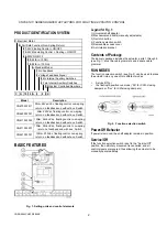
Page 2: ...ator into any one of two different modes Service Off or the floating 2 position run mode Dir for CCW closing dampers or Rev for CW closing dampers Fig 2 Function selection switch Power Off Behavior If power is removed the shaft adapter remains in position Service Off If the function selection switch is set to the Service Off position then all rotary movement is cancelled and all control signals ar...

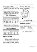
Page 3: ...ection switch setting only one manner of wiring is permitted see Fig 9 Table 2 Behavior of CN4605 CN4610 control signal at switch setting term 1 term 3 Dir Service Off Rev open open stops stops stops open 230 Vac stops stops stops 230 Vac open CW stops CCW 230 Vac 230 Vac CCW stops CW MANUAL ADJUSTMENT IMPORTANT To prevent equipment damage before manual adjustment you must remove power or set the ...

Page 4: ...nti rotation bracket is 3 35 in a max of 4 25 in is allowed see also Fig 11 Depending upon the specifics of your mounting site the actuator may shift in position slightly while tightening the screws at the top of the shaft adapter The anti rotation bracket features a T piece with a 5 mm long shank to accommodate for this movement It is important to ensure that this play is not impeded Universal Sh...

Page 5: ... these terminals must be equipped with spark suppression Table 4 Signals at terminals for CN4605 CN4610 terminal signal 1 L 230 V 2 N 230 V 3 control signal NOTE All cables connected to these terminals must be equipped with spark suppression Table 5 Internal end switches SSW2 terminal type of switch S1 common lead for switches A and B S2 S3 change over switch A S1 S2 opens and S1 S3 closes when sh...

Page 6: ...nal Inc Honeywell Tianjin Limited 1985 Douglas Drive North 66 BaiHe Road TEDA Golden Valley MN 55422 Tianjin 300457 P R C Printed in China on recycled paper containing at least 10 post consumer paper fibers CN05 CN10 SERIES DAMPER ACTUATORS FOR FLOATING 2 POSITON CONTROL CN0B 0544CH33 R0805B ...

Reviews: