CN20, CN34 SERIES DAMPER ACTUATOR FOR MODULATING AND FLOATING CONTROL
3
EN0B-0341CH33
R0803A
•
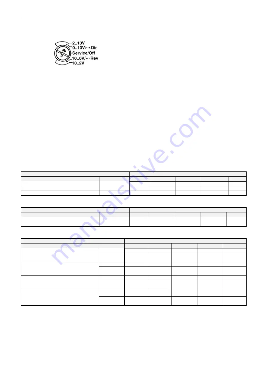
10-2V, modulating control; floating/2-position control, ccw
run
Fig.3. Function selection switch
Power-Off Behavior
If power is removed, the actuator retains its position.
Service/Off
If the function selection switch is set to the "Service/Off"
position, all rotary movement is cancelled, and all control
signals are ignored, thus allowing the actuator to be safely
manually operated.
Floating/2-Position Run Mode
If the function selection switch has been set to one of the four
positions (2-10V, 0-10V/Dir, 10-0V/Rev, 10-2V) – and the
actuator is wired as Floating/2-position mode (see A2 and A3)
– then as soon as operating power is applied, the actuator will
run clockwise or counterclockwise.
Modulating Run Mode
If the function selection switch has been set to one of the four
positions (2-10V, 0-10V/Dir, 10-0V/Rev, 10-2V) – and the
actuator is wired as modulating mode (see A1) – as soon as
operating power is applied, the actuator will run according to
the control signals applied. If terminal 5 is also wired, the
actuator will output the voltage feedback signal(0/2-10V)
proportional to actuator’s actual position. Alternatively, if
terminal 4 is wired and powered on, actuator will override the
control signal and immediately come to a position of 0% of
max. stroke.
Table 1 describes the actuator behavior (stops, rotates CCW,
or rotates CW) for the floating mode in relation to the control
signals applied to terminals 3 and 4 and to the function
selection switch setting.
Table 2 describes the actuator behavior (stops, rotates CCW,
or rotates CW) for the 2-position mode in relation to the
control signals applied to terminals 3 and 4 and to the function
selection switch setting.
Table 3 describes the actuator behavior (stops, rotates CCW,
rotates CW, runs in proportional position, or runs to 0% of
max. stroke) for the modulating mode in relation to the control
signals applied to terminals 3 and 4 and to the function
selection switch setting.
Table 1. Shaft adapter behavior in the floating mode
Control signal at
Function selection switch settings
Terminal 3
Terminal 4
2...10V
0...10V /Dir
Service / Off 10...0V /Rev
10...2 V
open open
stops stops stops stops stops
open 24
Vac/dc
CCW CCW stops
CW CW
24 Vac/dc
open
CW CW stops CCW
CCW
Table 2. Shaft adapter behavior in the 2-position mode
Control signal at
Function selection switch settings
Terminal 3
Terminal 4
2...10V
0...10V /Dir
Service / Off 10...0V /Rev
10...2 V
24 Vac/dc
open
CW CW stops CCW
CCW
24 Vac/dc
24 Vac/dc
CCW CCW stops
CW CW
Table 3. Shaft adapter behavior in the modulating mode
Control signal at
Function selection switch settings
Terminal 3
Terminal 4
2...10V
0...10V /Dir Service / Off 0...10V /Rev
10...2 V
open
-- -- stop -- --
Open
24 Vac/dc
0% (most
left)
0% (most
left)
stop
0%(most
right)
0% (most
right)
open
-- -- stop -- --
< min. control signal plus 0.24V
24 Vac/dc
0% (most
left)
0% (most
left)
stop
0%(most
right)
0% (most
right)
open
proportional proportional
stop
proportional proportional
between min. control signal plus 0.24V
and max. control signal minus 0.24V
24 Vac/dc
0% (most
left)
0% (most
left)
stop
0%(most
right)
0% (most
right)
open
-- -- stop -- --
> max. control signal minus 0.24V
24 Vac/dc
0% (most
left)
0% (most
left)
stop
0%(most
right)
0% (most
right)


