TERMINAL SETTINGS
EN1B-0022 IE10 R0717
6
Terminal Settings
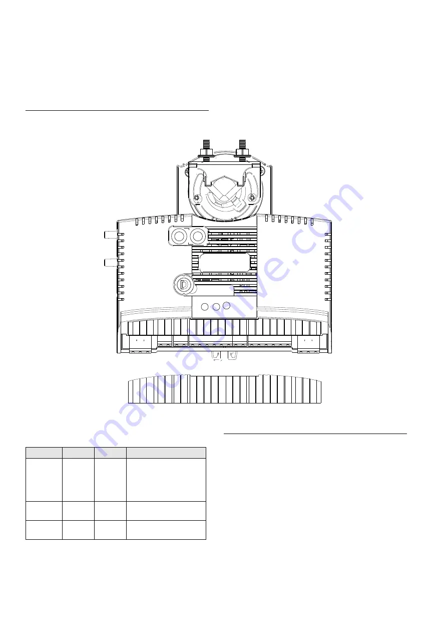
This section describes the terminal settings on the CPO-VAV2A controller.
CPO-VAV2A Terminal Overview
Figure 13 describes the layout of pins on the CPO-VAV2A controller.
Figure 13
Describes the layout of pins on the CPO-VAV2A controller.
LED operation
Automatic MAC addressing
Controllers with Automatic MAC addressing functionality can
be identified by a label covering the MAC address rotary
switches. This information is also printed on the product label
available on the controller. When a controller with Automatic
MAC addressing feature is powered ON, can assign its own
unique MAC address ranging from 1 to 30. It can also coexist
with other unitary controllers whose MAC addresses are set
manually. The controller can automatically adjust the MAC
address at any time to avoid duplicate addresses in the
network. The automatic MAC address assigned through this
process is retained when the controller is powered OFF.
To disable Automatic MAC addressing, remove the label on
the rotary switches and set the switches to the manual
485-
485+
FGND
S-BUS
S-BUS
AI1
AGND
AGND
Te
m
p
Set Point
ByPass/Fan
LED
AO2
AGND
AO1
DO6
COM
DO5
DO4
COM
DO3
FGND
N24V
AC
S24V
AC
Rx
Tx
Run
Declutch Button
Honeywell
Comfort Point
TM
Open
L
H
S1
S2
A B
C
D
E F
0 1 2 3
4 5
6 7 8
9
A B
C
D
E F
0 1 2 3
4 5
6 7 8
9
485-
485+
FGND
S-BUS
S-BUS
AI1
AGND
AGND
Te
m
p
Set Point
ByPass/Fan
LED
AO2
AGND
AO1
DO6
COM
DO5
DO4
COM
DO3
FGND
N24V
AC
S24V
AC
Sr.No
LED Label LED Color Description
1
Run
Green
The LED is Off when there
is no power to the controller.
LED is blinking when the
controller is working
normally.
2
Rx
Yellow
LED indicates Receive of
data on MS/TP bus.
3
Tx
Yellow
LED indicates Transmit of
data on MS/TP bus


