HONEYWELL 7000 SOLID STATE ALARM SYSTEM
69-1192—1
16
Table 6. Approved external sound devices.
Siren Manufacturer
Model
Ademco
747UL
Revere
R44SSD
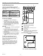
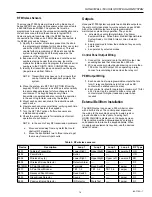
The following are general instructions for the bell or
horn installation. Follow the instructions specified for
the device to be used.
1.
Use UL-listed 18 AWG wire.
2.
Locate bell or horn within 200 ft of panel.
3.
Install bell or horn following manufacturer instructions.
4.
Connect a 3.3K ohm, 1/4 watt, resistor across HORN
terminal (TB1-18) and +13.8V (TB1-20) when no
external sounding device is used.
For tamper-protection of a bell or siren enclosure wire, wire
two leads from the external device NC tamper switch contacts
to a loop programmed as a tamper loop.
18
19
20
TB1
BELL
CMN
+13.8 VD
C
M10899
–
+
BELL/HORN
12 VDC @ 1 AMP MAX
Fig. 18. External bell/horn hookup diagram.
NOTE:
To meet CSFM requirements, the fire system must
use an ADEMCO Model 747UL Siren only.
Telephone Wiring
This connection is required for monitored installations or
whenever remote programming is desired. Proceed as
follows:
1.
Install the RJ-31X Phone Terminal Block within 25 ft of
the control panel.
2.
Use UL-listed 26 AWG wire or larger.
3.
Connect in accordance with Fig. 11 and 12.
4.
Program the Digital Receiver telephone number in the
Honeywell 7000 System panel only after all installation
and checkout has been completed, to avoid jamming
the panel buffer with repeated retries.
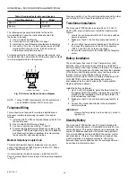
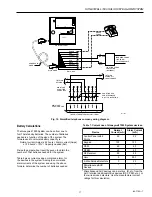
Modular Telephone Coupler Cord
This standard eight-conductor telephone cord is used to
connect the Honeywell 7000 System to the RJ-31X Phone
Terminal Block. See Fig. 19.
If not provided by the phone company, install the RF-31X
Phone Terminal Block in accordance with the wiring diagrams
in Fig. 19.
Plug one end into J1 on the control panel board and the other
end into the RJ-31X Phone Terminal Block. See Fig. 19.
Transformer Installation
The Honeywell 7000 System is powered by a 120 Vac to
24 Vac, 50A, plug-in transformer. Install the transformer as
follows:
1. Locate the control panel within 25 ft of a non-switched
power receptacle.
2. Make sure that S1, the control panel power switch, is
off.
3. Use UL-listed two-conductor twisted pair 18 AWG wire
to connect the transformer to the AC IN connectors
(TB1-21 and TB1-22) on the control panel.
4. Secure the transformer to the outlet with the faceplate
screw.
Battery Installation
The control panel has room for two 7 Ampere-Hour (AH)
batteries in the enclosure and can recharge up to 28AH of
battery capacity when longer standby is required. The system
supervises for the presence of battery and tests the operation
of the battery and charging system every two hours when ac
is present (every three minutes when ac is lost). A
disconnected, shorted or defective battery will indicate SYS
LOW BATTERY on the keypad display and must be
acknowledged by the user to silence the trouble audible.
Replace defective batteries.
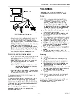
Install the battery as follows:
1.
Use 12 volt, rechargeable, gel-cell batteries rated for
the appropriate AH necessary to deliver the prescribed
standby for the installation. See the battery table and
load calculations that follow.
2.
Make sure that S1, the control panel power switch, is
off.
3.
Connect the control panel leads to the appropriate
battery terminals.
IMPORTANT
Observe battery polarity (red to positive [+], black to
negative [-]).
Standby Battery
The Honeywell 7000 System uses 7 AH gel-cell lead-acid
batteries for standby power. UL installations require 24 hour
of standby power. This section shows how to determine the
number of batteries needed for the system being installed.
One or two batteries can be installed in the system control
panel enclosure. If three or four batteries are needed, they
must be installed in a separate enclosure. The wiring
between these remote batteries and the control panel must
be enclosed in electrical conduit.

