HONEYWELL 7000 SOLID STATE ALARM SYSTEM
69-1192—1
19
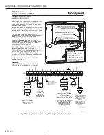
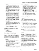
Fig. 20. Earth ground connection.
1.
Make the connection to earth ground with a single No.
18 AWG wire connected to the control panel box
ground stud. Secure the wire to earth ground with a
suitable clamp to make sure that it is a solid mechanical
and electrical ground.
2.
Avoid ground loops by connecting the shield of shielded
cables to the control panel box ground stud.
3.
Secure the corners of the control panel circuit board to
the metal box and connect a single earth ground wire to
the metal box ground stud located on the center right-
hand side. Do not loop or daisy-chain any wires on the
circuit board terminal blocks to this ground stud.
Powering Up and Disarming the System
1.
Power up the system. Make sure all keypad LED are off
and the keypad displays either FACTORY TEST or
MASTER ARM.
2.
If the keypad displays FACTORY TEST, program the
data base and download per instructions in the
Programming section.
NOTE:
After downloading is complete, enter a valid
passcode into the Honeywell 7000 System to
activate the new data base.
3.
Disarm the system by entering the programmed disarm
code (1 3 7 9) on any keypad. The keypad will indicate
SYSTEM DISARMED and READY.
The keypad will display AC POWER OFF if the ac is not
applied to the control panel.
The PEM has a status LED that is on steady when power is
first applied. After about 40 seconds, if the control panel
communicates successfully with the PEM, the LED will blink
at a one second on/off rate, after which the LED will blink five
times rapidly every time it communicates successfully with a
poll from the control panel.
This completes the physical installation of the system and
application of power. Proceed to the next section on
programming instructions.
BATTERY
TB1
J1
S1
M10905
GROUND STUD
PROGRAMMING
The following steps will enable Programming. Refer to
Programming Instructions, form 24510169, for details.
Setup
NOTE:
The following procedure steps apply to local
programming with a PC. If remote programming
(Downloading a program from the CSC) is
applicable skip steps 2 and 3: complete steps 4
through 7 to enable remote programming. The
system will be ready for the CSC to call, and the
system will connect, and the CSC program can be
downloaded. When complete select option 5 and
toggle the programming option to OFF.
1.
Disconnect the Telco connection at the Telco jack, J1,
on the Control Panel circuit board.
2.
Connect the PC (standard telephone) interface cable
from the PC Modem to the Telco Jack, J1, on the
Control Panel.
3.
Enter a valid passcode and verify the system disarmed.
Factory default passcode is 1379. Have user select a
new master passcode after installation is complete.
4.
Press the OPTIONS key and use the arrow keys to
scroll down to Option 5 “ALLOW PROGRAM”.
5.
Press “5” to allow programming. Enable Programming
will last 15 minutes then the system automatically
returns to disable local programming.
6.
Repeat the above procedure and press OPTIONS 6 to
enable the SERVICE Passcode to view EVENT LOG
records.
7.
Repeat the above steps 1 through 7 and press
OPTIONS 8 if RF testing or verification will be required.
Powerup
1.
Turn on the PC.
2.
Load and execute the System 7000 Programming
program.
3.
In the program set all customer options and system
values per the instructions in the next section.
4.
Download the data into the customers premise unit.
The panel will display: PROGRAMMING DONE
ENTER PASSCODE
5.
Enter Passcode and system will reset with the new data
base active. The system will come up MASTER ARM.
Enter passcode a second time to disarm.
6.
Repeat Option 7 to disable RF TEST MODE if
applicable.
NOTE:
Remote program changes after downloading will
only take effect after the passcode resets the
system.
Disconnect the PC Interface cable and reconnect the telco
line to the RJ31 phone service when finished with
programming (see next section).


