25
example.
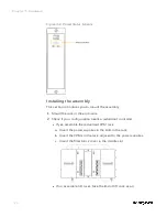
a.
Insert the power supply.
b.
Insert the PSM between the two power supplies.
c.
If a CPM will be inserted, set the mode switch for CPM
optionally.
d.
If a EPM will be inserted, set the EPM address and network
topology for the I/O rack using the rotary switch.
e.
Insert CPM or EPM as required.
3.
Install I/O modules.
ATTENTION: For each configured and labeled I/O module,
ONLY break off the "key-tabs" in the pattern that matches
that module type. For more information, see "Installing I/O
modules" in the
ControlEdge 900 Platform Hardware
Planning and Installation Guide
.
Wiring and cabling
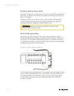
Terminal Block Wiring can be routed through the terminal block at
the top, at the bottom, or both. Wiring should be fixed in place using
wire ties at the slotted tabs that are molded in at top and bottom of
each terminal block. The terminal block is removable.
The optional Remote Termination Panel (RTP) provides an easy way to
connect the ControlEdge 900 Controller to the field wiring. The RTP
integrates some of the typical externally connected components,
reducing wiring and setup time. It also minimizes the need for
multiple wires under a single screw connection by expanding the
connectivity of the shared terminals of the I/O modules.
Chapter 3 - Hardware
Summary of Contents for ControlEdge 2020 SC-TEPL01
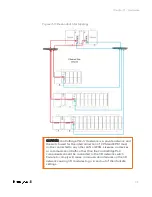
Page 28: ...Figure 3 8 Single star topology 28 Chapter 3 Hardware ...
Page 40: ...40 Chapter 3 Hardware ...
Page 66: ...66 Chapter 4 Software ...
Page 114: ...114 Chapter 6 Communication ...
Page 126: ...126 Notices ...

