background image

37

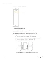
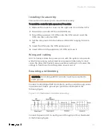
Installing the assembly

This section introduces you to mount the assembly.

To install the controller with expansion I/O modules

1.

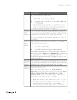
Remove the connector cover on the right side of controller IOTA.

2.

Mount the controller IOTA onto the DIN rail.

3.

Mount the expansion I/O IOTAs onto the DIN rail and insert the
IOTA into the controller IOTA.

4.

Set the rotary switch to the address of the IOM, ranging from 1 to
99.

5.

Insert the CPM onto the IOTA and secure it.

6.

Insert IOM onto the expansion I/O IOTA and sure it.

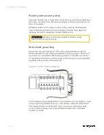
Wiring and cabling

All I/O channels share the power source with the system components
while the two analog output devices are powered internally. In most
cases, the other 26 channels require external cabling to introduce the
voltage to field loops from the system power source.

Grounding and Shielding

CAUTION: ControlEdge 2020 controller must be connected to
earth ground.

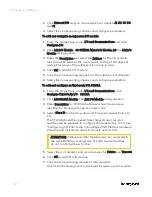
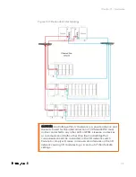
Connect ControlEdge 2020 Controller to earth ground through power
input terminal chassis ground pin (pin 33) as illustrated in the
following figure.

Figure 3-15: Redundant Controller Grounding

Connect Expansion I/O to earth ground through pin 31 as illustrated
in the following figure.

Chapter 3 - Hardware

Summary of Contents for ControlEdge 2020 SC-TEPL01

Page 1: ...ControlEdge PLC and ControlEdge RTU Getting Started RTDOC X287 en 152A April 2019 Release 152 ControlEdge PLC ControlEdge RTU ...

Page 2: ...al Sàrl While this information is presented in good faith and believed to be accurate Honeywell disclaims the implied warranties of merchantability and fitness for a purpose and makes no express warranties except as may be stated in its written agreement with and for its customer In no event is Honeywell liable to anyone for any direct special or consequential damages The information and specifica...

Page 3: ...wer on 31 ControlEdge 2020 platform 31 Hardware components 32 Installing the assembly 37 Wiring and cabling 37 I O network topology 39 Power on 39 Chapter 4 Software 41 Installing ControlEdge Builder 41 Launching ControlEdge Builder 41 Checking firmware versions 42 Creating a project 42 Configuring hardware 44 Setting controller name 44 Configuring the controller IP address 44 Configuring controll...

Page 4: ...troller 67 Downloading a project to the controller 68 Configuring date time 69 Setting time source 69 Setting time zone 70 Upgrading firmware 70 Upgrading firmware for a non redundant controller 71 Upgrading firmware for a redundant controller 72 Upgrading EPM firmware 75 Upgrading ControlEdge 900 I O module firmware 76 Upgrading serial module firmware 77 Upgrading ControlEdge 2020 Expansion I O f...

Page 5: ...PC UA server 99 Publishing to Experion 100 Configuring DNP3 Slave 100 Communicating with Experion via DNP3 102 Configuring a DNP3 slave 102 Publishing to Experion 102 Configuring HART 103 Configuring a HART IP Server 103 Configuring a HART Function Block 104 Configuring CDA 106 Installing ControlEdge integration service 107 Configuring a CDA Responder 108 Publishing to Experion 110 Configuring Wir...

Page 6: ...icense 115 Configuring FDM for ControlEdge PLC RTU network 116 Building networks 118 Chapter 8 Security 119 Logon feature 119 Setting operating modes 119 Built in Firewall 122 Configuring IPsec 122 Notices 124 6 Contents ...

Page 7: ...oft Windows environment are required Introduction to ControlEdge Technology Item Description ControlEdge PLC ControlEdge 900 controllers running the eCLR IEC 61131 3 execution environment with PLC software options configured with ControlEdge Builder ControlEdge RTU ControlEdge 2020 controllers running the eCLR IEC 61131 3 execution environment with RTU software options configured with ControlEdge ...

Page 8: ...s all the properties of an EtherNet IP device necessary for a Scanner module to communicate with it EDS files my be used in the first step of creating an I O module or device type for interfacing to an EtherNet IP device EPM Expansion Processor Module Expansion I O rack I O rack with EPM installed Expansion IOM I O Module IOM external to the CPM that expand the I O capacity FDAP Field Device Acces...

Page 9: ...PM Right End Plate A right end plate is required at the end of each row of expansion I O modules including the row connected to a controller It allows additional rows to be added or terminates the I O network RIUP Removal and Insertion Under Power RPI Requested Packet Interval The repetitive interval by which assemblies are periodically transported over EtherNet IP I O connections between Producer...

Page 10: ...uilder Software Change Notice n ControlEdge Builder User s Guide n ControlEdge 900 Platform Hardware Planning and Installation Guide n ControlEdge Builder Function and Function Block Configuration Reference n ControlEdge Builder Protocol Configuration Reference Guide n ControlEdge PLC and ControlEdge RTU Network and Security Planning Guide n ControlEdge EtherNet IP User s Guide n ControlEdge_PLC_I...

Page 11: ...ument does not provide any detailed instructions Please refer to other related documents and online helps embedded in ControlEdge Builder for more information Make sure all the hardware modules used in the system are installed with the right firmware version and the engineering station has the latest ControlEdge Builder You can find the firmware and software updates on http honeywellprocess com wi...

Page 12: ...twork in the system as a failure or loss of service on this network can result in loss of control On the level 2 network the Engineering Workstation third party devices HMI and SCADA connect to the switch at this level A failure of this level network may result in a loss of view of the process if HMI or SCADA is employed The two network levels must be isolated with each other ETH1 ETH2 ports are r...

Page 13: ...MI SCADA or Engineering Workstation I O network is the most critical network in the system as a failure or loss of service on this network can result in loss of control At control network Engineering Workstation third party devices HMI and SCADA connect to the switches A failure of this level network may result in a loss of view for operator of the process if HMI or SCADA is employed The two netwo...

Page 14: ...uring Modbus on page 83 for more information See Modbus Slave Configuration on page 1 for more information 4 See Configuring OPC UA on page 94 for more information 5 See CDA Configuration on page 1 for more information 6 See FDM integration on page 115 for more information 7 See Security on page 119 for more information 8 See Configuring Wireless I O on page 111 for more information 9 See Configur...

Page 15: ...users and OEMs to assemble a system that fits a broad range of requirements Any configuration can be readily modified or expanded as requirements dictate ControlEdge PLC can be deployed standalone or with a SCADA system such as Experion Item Model number Description 1 900RR0 0200 Redundant CPM Rack 2 900R04 0200 I O Rack 4 slot 15 ...

Page 16: ...ardware components This section provides a description of the major components that can be included in a ControlEdge 900 Controller physical configuration and indicates how the components can be combined Some of the components are required in all configuration Others are optional and can be used to provide additional functions or to size the system or to modify or expand the system to meet changin...

Page 17: ...e quantity of the slots Figure 3 1 Redundant CPM Rack Components Item Description 1 Redundant CPM rack 2 Redundant Switchover Module Slot Filler 3 Primary Secondary CPMs 4 Two Power Supplies Figure 3 2 I O rack with non redundant power supply Chapter 3 Hardware ...

Page 18: ...or EPM with Security Cover 4 Grounding bars for I O wiring optional required for safety applications 5 Input Output modules 6 I O Terminal Blocks 7 Power Status Module PSM required if using redundant power supply Control Processor Module CPM CPM 900CP1 0200 contains most of the electronics required to perform the function of a process controller A redundant CPM rack contains two CPMs Either CPM ca...

Page 19: ...s the area is known to be non hazardous 4 Mode switch There are four mode switch positions on CPM STOP RUN and two REMOTE positions Two REMOTE positions are identical Rotate the four positions in clockwise or counter clockwise When the mode switch is in REMOTE position the operating modes can be configured in the Configuration tool For more information for the operating modes see Selecting operati...

Page 20: ...nnection between redundant CPM in Ring topology 7 Ethernet LED status indicators for communications functions Expansion Processor Module EPM EPM 900SP1 0200 is installed in the expansion I O rack and provides the link between the CPM and remote I O modules The EPM is shown in the following figure Item Description 1 Status LED indicator for EPM functions 2 Role LED indicator for EPM functions 3 Eth...

Page 21: ...network topology Input Output module ControlEdge PLC supports the following I O modules For more information see I O module specification in the ControlEdge 900 Platform Hardware Planning and Installation Guide Model number I O module 900U01 0100 Universal Input Output Module UIO 900A01 0202 Universal Analog Input Module UAI 900A16 0103 High Level Analog Input Module 16 channels 900B01 0301 Analog...

Page 22: ...Input Frequency Input Module 4 channels Power supply Both AC power supply 900P01 0301 and DC power supply 900P24 0301 can be used in Redundant CPM rack Local I O rack and Expansion I O rack For more information see Power supply in the ControlEdge 900 Platform Hardware Planning and Installation Guide Figure 3 4 AC Power Supply 22 Chapter 3 Hardware ...

Page 23: ...hown in the following figure sits between redundant power supplies on the I O rack It is a status module for both power supplies and indicates which are powered PS 1 left or PS 2 right or both typical When the status indicator for either or both of the power supplies is lit it is reporting that the status of the associated power supply is good and that the outputs are within specified limits When ...

Page 24: ...Check if your configuration needs a redundant controller l If yes assemble the redundant CPM rack a Insert the power supplies in the slots in the rack b Insert the CPMs in the rack adjacent to the power supplies c Insert the filler block cover in the middle slot l If no assemble I O racks take the 8 slot I O rack as an 24 Chapter 3 Hardware ...

Page 25: ...tform Hardware Planning and Installation Guide Wiring and cabling Terminal Block Wiring can be routed through the terminal block at the top at the bottom or both Wiring should be fixed in place using wire ties at the slotted tabs that are molded in at top and bottom of each terminal block The terminal block is removable The optional Remote Termination Panel RTP provides an easy way to connect the ...

Page 26: ...ounding Aluminum grounding bars for I O wiring are available as options When selected for use they are fastened to the top and or bottom of each rack as indicated in the following figure To enable connection of multiple ground wires with a single screw the wires can be twisted together and secured with a wire lug Figure 3 7 Wire Shield Grounding To facilitate module replacement it is advisable in ...

Page 27: ...ler system It includes provisions for communication via Ethernet with host systems and the Ethernet ports provide a layer of protection against cyberattacks Honeywell recommends use of Solarwinds and or Honeywell Risk Manager to detect unintended and excess network traffic ControlEdge PLC supports star and ring I O topologies for I O communication Star Topology The following diagram shows an examp...

Page 28: ...Figure 3 8 Single star topology 28 Chapter 3 Hardware ...

Page 29: ...CPM and EPM must not be connected to any other LAN or WAN Likewise no devices or communication traffic other than the ControlEdge PLC components should be connected to the I O network switch Failure to comply will cause communication failures on the I O network causing I O modules to go in and out of their failsafe settings Chapter 3 Hardware ...

Page 30: ... ETH4 must be connected to CPM port 3 ETH3 or EPM port 1 ETH1 n EPM port 1 ETH1 must be connected to EPM port 2 ETH2 or CPM port 4 EHT4 n EPM port 2 ETH2 must be connected to EPM port 1 ETH1 or CPM port 3 EHT3 For more information see Planning for network topology in the ControlEdge 900 Controller Hardware Planning and Installation Guide 30 Chapter 3 Hardware ...

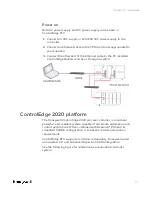
Page 31: ...tly or through a switch ControlEdge 2020 platform The Honeywell ControlEdge 2020 process controller is a modular powerful and scalable system capable of all remote automation and control applications When combined with Experion PKS and its simplified SCADA configuration it solves the remote automation requirements ControlEdge RTU supports controller redundancy Honeywell wired and wireless I O and ...

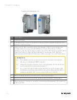
Page 32: ...2020 expansion I O right end plate includes a CAT 5 termination cable 4 SC TEPL01 ControlEdge 2020 expansion I O left end plate Hardware components ControlEdge RTU system consists of a controller expansion I O modules right end plate and left end plate These components are combined with field devices to make a complete system Redundant Controller The redundant controller consists of two CPMs and a...

Page 33: ... SLOT2 5 Screw hole used for locking controller IOTA and expansion I O IOTA 6 Expansion Connector used for connecting with expansion I O module Expansion I O An Expansion I O consists of an IOM and an IOTA An I O Module IOM contains most of the electronics required to perform a specific I O function The IOM plugs onto the IOTA ATTENTION Up to 30 expansion IOMs of Revision B can be connected with t...

Page 34: ...OM on page 1 for more information ATTENTION l The address must be unique across all I O modules connected to the same ControlEdge 2020 controller l Unless the location is known to be non hazardous do not adjust the switches while the equipment is powered l Do not set the switch index bigger than 98 or else the system LED of IOM status indicator would blink with yellow reflecting that IOM is unable...

Page 35: ...ght end plate is required at the end of each row of expansion I O modules including the row connected to a controller It allows additional rows to be added or terminates the I O link The right end plate has two Ethernet ports and a left expansion connector as numbered in the following picture Figure 3 13 Right End Plate Item Description 1 Left expansion connector connects to a controller or an exp...

Page 36: ...onnection Left end plate has an 18 30 VDC Power Input two Ethernet ports and a right expansion connector as numbered in the following picture Figure 3 14 Left End Plate Item Description 1 18 30 VDC power supply 2 Right expansion connector connects to an expansion I O module 3 Screw holes used for locking left end plate and expansion I O IOTA 4 5 Ethernet port 1 and Ethernet port 2 extends the I O ...

Page 37: ... O IOTA and sure it Wiring and cabling All I O channels share the power source with the system components while the two analog output devices are powered internally In most cases the other 26 channels require external cabling to introduce the voltage to field loops from the system power source Grounding and Shielding CAUTION ControlEdge 2020 controller must be connected to earth ground Connect Con...

Page 38: ...dant Controller Grounding Figure 3 17 Expansion I O Grounding For more information about each I O module wiring see I O Wiring in the ControlEdge 2020 Platform Hardware Planning and Installation Guide 38 Chapter 3 Hardware ...

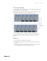
Page 39: ... an example of the topology For more information see Planning for network topology in the ControlEdge 2020 Controller Hardware Planning and Installation Guide Power on 1 Connect 24 VDC supply to the controller 2 Connect an Ethernet cable to the port most appropriate for your situation 3 Connect the other end of the Ethernet cable to the PC installed ControlEdge Builder directly or through a switch...

Page 40: ...40 Chapter 3 Hardware ...

Page 41: ...ve 2 Browse to the folder containing ControlEdge_builder_setup exe Double click this file 3 Follow the screen prompts to install ControlEdge Builder For full instructions on how to install ControlEdge Builder see the ControlEdge Builder Software Installation User s Guide Launching ControlEdge Builder Click Start All Programs Honeywell ControlEdge Builder ControlEdge Builder to launch ControlEdge B...

Page 42: ...project To create a new project 1 From the Start Page click Create Project 2 In the Create New Project from Template window click General and select the target template from the Available Templates list l Select 900cp1 to create a project for a ControlEdge 900 controller l Select SC UCMX01 or SC UCNN11 to create a project for a ControlEdge 2020 controller l SC UCMX01 is for a non redundant control...

Page 43: ... area contains toolbar and menu bar You can navigate to IEC Programming Workspace compile a project build a project debug on off etc 2 This area contains the following options open an existing project connect a controller upgrade a project and download a project 3 This area contains configuration options for the controller and project You can configure the IP address configure I O upgrade firmware...

Page 44: ...y default network settings If your controller has been previously configured these settings may have been changed Port Default setting ETH1 IP address is dynamically assigned from a DHCP server If no DHCP server is found by the controller an IPv4 link local address will be assigned 169 254 x x ETH2 Static IP address 192 168 1 50 Table 4 1 Factory default network settings of the non redundant contr...

Page 45: ...ler this feature is only applicable when the mode switch is in REMOTE position Under Controller and Programming select Configure Controller Start Up the Configure Controller Start Up page appears There are four options for controller start up n Last operating mode or Running after an abnormal stop This option is the default setting for ControlEdge 2020 controller The controller will start in the o...

Page 46: ...e controller was stopped abnormally before power off the controller will start in Stopped mode n Running The controller will warm start in Running mode If the warm start fails the controller will go to Stopped mode n Stopped The controller will start in Stopped mode ATTENTION If you reboot the controller manually the configuration in this section will not take effect For example If you select Runn...

Page 47: ...of ETH1 and ETH2 were disabled configure the Secondary Controller IP Address manually Configuring an I O module Configure an I O module for ControlEdge 900 controller 1 From the Home Page under I O and Communications and click Configure Modules Configure I O Modules 2 Click Add I O Module the Add I O Module dialog appears 3 Select the Type assign the Rack and Slot and set the IOM Scan Time for the...

Page 48: ...ome Page under I O and Communications click Configure Third Party I O ST103A 2 Click Add ST103A Module The Add I O Module dialog appears 3 Enter Description for ST103A module which will be a unique identifier for binding with specific meter runs 4 Select Slave ID for the drop down list The valid value is from 1 to 15 The ST103A should be opened to set Slave ID and row 4 bit switches will be availa...

Page 49: ...ddress l If controller redundancy is enabled the rack address range is from 1 to 99 l If controller redundancy is disabled the rack address range is from 0 to 99 0 is only for the local I O rack l For an expansion I O rack the address must be the same with the EPM address configured on 1x and 10x rotary switches For details about the rotary switches see Assembling I O racks in the ControlEdge 900 ...

Page 50: ...ts is set as 8 by default Stop Bits 1 2 For RS232 1 and RS232 2 you should configure one more option Flow Control See the following table for the parameter descriptions Parameter Description Flow Control Only for RS232 1 and RS232 2 l None l RTS CTS l RTS 6 Under Protocol Binding select a protocol from the Port Protocol drop down list The following table provides information about various protocol...

Page 51: ... you select Modbus ASCII Slave you must configure two more options Slave ID and Mapping If the Mapping is empty you must add a mapping table first See Adding a Modbus Slave mapping table on page 1 for more information Modbus ASCII Master The controller acts as the Modbus Master and used for communication between The controller and third party Modbus Slave devices for example I O modules User Defin...

Page 52: ...dates if a data frame is sent completely If the received data frame has same characters with the End Delimiter system regards it has already received a complete data frame The default setting is blank which means this option is disabled For how to configure User Defined protocol see User Defined Protocol in the ControlEdge Builder Function and Function Block Configuration Reference 7 Click Save to...

Page 53: ...ontroller simulator Yes Debug a program Yes Force I O value through I O variables Yes Force I O value through I O channels No Upload system event log Yes Monitor link status Yes System diagnostics Yes Secure communication No Communication between SCADA and controller simulator Yes Communication between controller simulators Yes Communication between virtual and physical controllers Yes Modbus TCP ...

Page 54: ... 0 or higher hypervisor For more information see the vendor s documents 2 Import or open an OVA file in the virtual machine and play the virtual machine Honeywell provides three OVA files stored in Simulator folder in the Media RXXX indicates the release number l ControlEdge 900 controller ControlEdge_PLC_900CP1_ RXXX ova l ControlEdge 2020 controller l Non redundant controller ControlEdge_RTU_SCU...

Page 55: ...ocation stored the target OVA file select the OVA file and click Open c From the Import Virtual Machine dialog name the virtual machine and select a storage location for the virtual machine Click Import Chapter 4 Software ...

Page 56: ...l machine e For ControlEdge 900 controller you should configure the controller type l Enter 0 to configure the controller type as non redundant l Enter 1 to configure the controller type as redundant 56 Chapter 4 Software ...

Page 57: ...r on page 1 for more information After you connect to a controller simulator make sure the build settings is I486_LE_GCC3 Click IEC Programming Workspace and check the following parameter 4 Configure a controller simulator See the table above for the supported configuration Project version must match with the controller simulator version 5 Compile the project See Compiling a project on page 1 for ...

Page 58: ...well for specific hardware The file extension for firmware library is fwl For more information about the function and function block see the ControlEdge Builder Function and Function Block Configuration Reference Guide To add a library 1 Click IEC Programming Workspace from the toolbar or from Home Page click Program with IEC61131 3 2 Right click Libraries and click Insert Select User Library or F...

Page 59: ...related information for this channel is grouped together in the structures as shown below You can use this information as reference for I O channel configuration and programming Table 4 3 I O channel structures of the I O_DataTypes Structure type Parameter Parameter type ANALOG_INPUT_TYPE STS USINT PV REAL EUHI REAL EULO REAL EUHIEX REAL EULOEX REAL ANALOG_OUTPUT_TYPE OP REAL ANALOG_OUTPUT_READBAC...

Page 60: ...e counted over a specified Sample Time and scaled to EU Second EU Minute or EU Hour 3 PREI Preset indicator OFF 0 when COUNTER less than the local or remote preset value ON when the count reaches the local or remote preset value The hardware module determines the state of the PREI output PREI is cleared by the RST input A preset value of 0 effectively turns off the Preset allowing the counter to c...

Page 61: ...ct Insert variable to add a new I O variable For output channel variables you must add corresponding read back variables with suffix _READBACK in the Input I O Variables group 5 Double click the Name and Description fields to modify and select Type and Usage from the drop down lists The maximum quantity of characters for a variable name is 30 IEC address of the I O variable is generated automatica...

Page 62: ...tion of function or function block calls Programs have input and output parameters and they can have an internal memory n Function Block POUs with multiple input output parameters and internal memory n Function POUs with multiple input parameters and exactly one output parameter To create a POU 1 Click IEC Programming Workspace from the toolbar or from Home Page click Program with IEC61131 3 2 Fro...

Page 63: ... name or enter a new name or select an already existing name from the Name combo box 11 Select the Data Type and Usage from the drop down lists l If you are creating a Program there are two options for Usage VAR and VAR_GLOBAL l If you are creating a Function Block there are five options for Usage VAR VAR_INPUT VAR_OUTPUT VAR_IN_OUT and VAR_ GLOBAL l If you are creating a Function there are two op...

Page 64: ...he maximum quantity of characters which a task name can have is 7 and that of a program instance is 24 4 Select the Task type See the following table for the descriptions of task types Task type Description DEFAULT Each resource can contain one default task It is the task with the lowest priority lower than cyclic tasks and is not time scheduled CYCLIC Cyclic task executes their associated program...

Page 65: ... announced user library has been changed The command Rebuild Project should only be used if Make generates compiling errors or you have unzipped your project without the frontend code While compiling the message window displays the compilation process Any detected errors and warnings e g syntax errors memory or file problems and additional information are also displayed in the appropriate message ...

Page 66: ...66 Chapter 4 Software ...

Page 67: ...ct the controller type l ControlEdge 2020 controller l ControlEdge 2020 controller simulator l ControlEdge 900 controller l ControlEdge 900 controller simulator 3 Select the user name and enter the password 4 Click Connect If the current and previously connected controller types are different the following dialog appears Click OK to automatically configure the settings TIP Due to the cyber securit...

Page 68: ... From the Home Page click Download A eclrRes window appears For more information about the items in the eclrRes window see the embedded online help Select Help Contents and search for PLC state machine to display the corresponding content 2 A Download confirmation dialog appears to make sure you want to download Click Yes ATTENTION If you want to upload this project in the future you should select...

Page 69: ...e Page under Miscellaneous click Configure Date Time Options 2 Select Enable and enter the IP addresses of SNTP servers in the Primary Server and Secondary Server fields If you select Enable here under Configure ProtocolsDNP3 Slave you should not select Enable DNP3 Time Synchronization in Application Layer tab at the same time 3 Adjust the Poll Interval to synchronize current controller time to th...

Page 70: ...hird party ISA100 2011 device the controller must be upgraded to R140 or later releases and FDAP must be upgraded to OW R300 n For ControlEdge 2020 controller l You can upgrade firmware from R110 to R151 R140 to R151 R150 to R151 directly For other versions please contact with GTAC l Expansion I O modules must be upgraded before controllers n For ControlEdge 900 controller make sure the CPM versio...

Page 71: ...ng when you transfer the firmware to the controller and will be stopped when you upgrade the firmware So when the controller is running we provide the interactive mode to control when the controller stops l If you select the Interactive mode a dialog appears confirming that the transfer is complete Click Next to upgrade the firmware and the controller is stopped You can also click Cancel to quit t...

Page 72: ...ing or Stop Locked operating mode You can rotate the mode switch on CPM to change the operating mode see CPM mode switch in ControlEdge 900 Platform Hardware Planning and Installation Guide If the mode switch is in the REMOTE position See Setting operating modes on page 1 for more information Prerequisites n Assume the primary CPM is at slot A and the secondary CPM is at slot B n Both primary slot...

Page 73: ...rmware with Off process procedure ATTENTION This procedure could cause loss of control in an operating process ATTENTION For ControlEdge 2020 controller if the controller is connected with I O modules you must stop the program before performing the off process procedure 1 From the Start Page click Connect to connect the target primary CPM slot A 2 From the Home Page select Upgrade Firmware under M...

Page 74: ...ct the controller 10 The firmware upgrades 11 Perform the relevant procedures for ControlEdge 2020 controller and ControlEdge 900 controller l For ControlEdge 2020 controller a Click OK The primary CPM synchronizes the firmware with the secondary CPM and upgrades the firmware of the secondary CPM automatically b To check whether the secondary CPM upgrade is complete click Connect from the Home Pag...

Page 75: ...chronization first To upgrade EPM 1 From the Start Page click Connect to connect the target controller 2 From the Home Page select Upgrade Firmware under Maintenance The Upgrade Firmware dialog appears 3 Click EPM tab all available EPMs are displayed At least one I O module which is in the same rack with the target EPM must be added in the Configure I O page then the target EPM will be displayed h...

Page 76: ...p Locked Running or Stopped operating modes ATTENTION The target I O module must be added in the Configure I O page See Configuring I O modules and channels on page 1 for more information To upgrade I O module 1 From the Start Page click Connect to connect the target controller 2 From the Home Page select Upgrade Firmware under Maintenance The Upgrade Firmware dialog appears 3 Click the UIO 16 tab...

Page 77: ...e Serial module firmware upgrade is ONLY allowed in Stop Locked Running or Stopped operating modes ATTENTION The target serial module must be added in the Configure Serial Modules page See Configuring serial modules on page 49 for more information To upgrade serial modules 1 From the Start Page click Connect to connect the target controller 2 From the Home Page select Upgrade Firmware under Mainte...

Page 78: ... Click OK Upgrading ControlEdge 2020 Expansion I O firmware ATTENTION It is recommended to upgrade the firmware without opening a project 1 From the Start Page click Connect to connect the target controller 2 From the Home Page select Upgrade Firmware under Maintenance The Upgrade Firmware dialog appears 3 Click Expansion I O tab all available expansion I Os are displayed 4 Select or multiselect t...

Page 79: ...cation firmware which handles the functioning of the sensor in the device This can also be upgraded over the wireless network For more information about upgrading the firmware of field devices refer to the field device vendor s documentation Honeywell field devices usually have separate firmware files for radio firmware and application firmware FDAPs have only radio firmware ATTENTION If either of...

Page 80: ... Upgrade The Application Radio Firmware Upgrade dialog box closes The Firmware Upgrade Status dialog box displaying the status of the upgrade appears Closing the dialog box allows the upgrade operation to run in the background Once the upgrade is complete the status column displays the status as complete If firmware upgrade fails for a device you can abort the upgrade and start again To abort firm...

Page 81: ...n the list perform the following steps to open the firmware file a Click Add to browse to the directory location of the firmware upgrade file b Select the target firmware upgrade file and click Open Firmware files are stored in volatile memory due to memory limitations in the controller Hence these files will be removed on power cycle 4 Click Upgrade The Firmware Upgrade Status dialog box appears ...

Page 82: ...archived as a zip file in the controller See Downloading a project to the controller on page 1 for more information To upload a project 1 From the Home Page select More Project Upload The Upload Confirmation dialog appears 2 There are two options l Click Open If a project is already open when you upload this project the open project will be saved and closed The uploaded project is saved to the fol...

Page 83: ...n to the Home Page 5 Click Configure Protocols Modbus Slave select the target Ethernet or serial port you want to bind 6 Select Slave ID 7 For Ethernet ports configure the TCP port number 8 Select the required mapping table from the Mapping drop down list If the list is empty you should add a mapping table first See Adding a Modbus Slave mapping table in the ControlEdge Builder User s Guide The sa...

Page 84: ...ort 4 Click Save to save the configuration and click Back to return to the Home Page 5 Click Connect from the Home Page to connect a controller 6 Click Download from the Home Page to load the configuration of Modbus TCP Master to the controller 7 Click IEC Programming Workspace from the toolbar 8 Right click Logical POUs and select Insert Program to add a new POU 9 Under Physical Hardware right cl...

Page 85: ...al values to CONFIG_INFO CONFIG_INFO a predefined data structure for Modbus configuration information is the crucial input for Modbus master function blocks and contains key Modbus communication parameters such as IP address of slave slave ID port number of the controller to be used etc This data structure is read only and cannot be viewed and edited in ControlEdge Builder See Description of CONFI...

Page 86: ... 18 Click Make from the toolbar to compile the programs 19 Click Download from the toolbar to download the compiled programs of Modbus TCP Master to the controller Configuring a Modbus Serial Master Modbus Serial Master is used for communication between the controller and third party Modbus slave devices over serial port It is only applicable for ControlEdge RTU 86 Chapter 6 Communication ...

Page 87: ...ud Rate 300 600 1200 2400 4800 9600 19200 38400 57600 115200 RS232 does not support 57600 and 115200 Parity None ODD EVEN Data Bits 7 8 Stop Bits 1 2 Table 6 1 Serial Port Parameters For RS232 1 and RS232 2 there are two more options to configure Flow Control and Force Online See the following table for the parameter descriptions Parameter Description Flow Control Only for RS232 1 and RS232 2 l No...

Page 88: ...at will happen for Force Online option between the controller and the device it communicates Controller Force Online Option Third party Device Force Online Option Communication Enabled Enabled Normal Disabled Enabled Normal with energy saving on the controller Enabled Disabled Normal with energy saving on Device Disabled Disabled It is forbidden Both devices would consider there is no device conne...

Page 89: ...ges in ControlEdge Builder User s Guide 6 Click Download from the Home Page to load the configuration of Modbus Serial Master to the controller 7 Click IEC Programming Workspace from the toolbar 8 Right click Logical POUs and select Insert Program to add a new POU 9 Under Physical Hardware right click Task and select Insert Task to add a task 10 Right click the task you have inserted and selectIns...

Page 90: ...r function block to assign variables In the pop up Variable Properties window select the Name Data Type and Usage from the drop down list and assign Initial value and I O address Then click OK To assign initial values to CONFIG_INFO CONFIG_INFO a predefined data structure for Modbus configuration information is the crucial input for Modbus master function blocks and contains key Modbus communicati...

Page 91: ...nction block to variables to monitor DATA1 is the variable name assigned by the user of OUTPUT pin of MB_RD_MHR and it is an array After the basic programming steps as described the workplace will appear as shown below Chapter 6 Communication ...

Page 92: ...for a variety of manufacturing automation applications including control safety synchronization motion configuration and information ControlEdge 900 controller supports an efficient EtherNet IP interface The EtherNet IP interface facilitates a comprehensive integration between ControlEdge 900 controllers and the EtherNet IP compatible nodes and I O devices ControlEdge Builder provides options to c...

Page 93: ...you must register EDS files first 3 Configure EtherNet IP devices l Configure EtherNet IP devices using EDS file l Configure generic EtherNet IP devices Configuring an EtherNet IP server 1 Bind EtherNet IP Server to ETH1 or ETH2 Only one port can be bound at a time 2 Select EtherNet IP for variables which will be read and write by EtherNet IP client Configuring communication with third party contr...

Page 94: ...ta types communicating with third party controllers Configuring OPC UA ControlEdge 900 controller supports OPC UA server and client which are built in protocols in the controller and it provides an IIoT ready open platform that enables users to better leverage data across their assets This chapter introduces how to quickly configure OPC UA Server and OPC UA client For more information see OPC UA C...

Page 95: ...C UA Sever and OPC UA client below key parameters of Server must be provided and be required in the configuration in OPC UA side Server Endpoint URL The URL of ControlEdge 900 controller OPC UA Server defined as follows ControlEdge 900 controller OPC Server URL opc tcp IP Port opc tcp is the protocol string portion of the URL This string is constant since the protocol used by the ControlEdge 900 c...

Page 96: ...hose defined by companion specifications or the local server The ObjectTypes defined in the UA specification for IEC 61131 3 derive from the OPC UA Device Integration Types which in turn derive from the OPC UA Core ObjectTypes Thus the ControlEdge 900 controller OPC UA Server includes these 3 namespaces in addition to its own namespace The list of namespaces used in the Server is shown below Names...

Page 97: ...the ParameterSet and the GlobalVars object components of eclrRes shown in section 6 1 the BrowseName for ParameterSet will use DI namespace and the BrowseName for GlobalVars will use the PLC namespace Namespace Uri is used for OPC UA client to get the NameSpaceIndex Configuring an OPC UA Client This section only introduces simple procedures to configure the OPC UA Client For more information see O...

Page 98: ...on the target OPC UA server ATTENTION Make sure that the OPC UA client s time is synchronized to the controller s time To configure an OPC UA client 1 Click Configure Protocols OPC UA Client The OPC UA Client page appears 2 Select the values for the Max Session Count and Max Subscription Per Session parameters It is recommended to use the default values See the following table for the parameter de...

Page 99: ...must be enabled on the Ethernet port s connected to the same network as the Experion Server Experion can read write and monitor global variable program local variable and function block instance variable through the Identifier defined by OPC UA protocol The maximum length of the Identifier is 73 characters Global variable s Identifier is GV Varname Program local variable s Identifier is Program In...

Page 100: ...rion For how to publish the configuration to Experion See Publishing to Experion on page 110 for more information Configuring DNP3 Slave DNP3 is used for communication between the controller and a DNP3 master such as a SCADA system like Experion The controller acts as a DNP3 slave Binding protocol to Ethernet ports 1 From the Home Page of ControlEdge Builder click the arrow beside Configure Ethern...

Page 101: ...r Miscellaneous Configure Date Time options at the same time or else you cannot download your configuration 5 In the Mapping tab and select the required mapping table from the Mapping drop down list If the list is empty you should add a mapping table first See Adding a DNP3 Slave mapping table in the ControlEdge Builder User s Guide The same mapping table may be selected for use on multiple ports ...

Page 102: ... or ETH2 2 Under Network Setting select Use the following IP address and enter the details in the IP Address Subnet Mask and Gateway fields 3 Under Protocol Binding select DNP3 to for the Ethernet port 4 Click Save to save the configuration and click Back to return to the Home Page 5 Click Make to compile the configuration to the controller Publishing to Experion This function enables the user to ...

Page 103: ...ties n HART IP client FDM communication n HART Function Block communication The controller enables the HART IP client to exchange information with HART field devices connected to the AI AO channels in the controller via a HART IP Server The controller enables HART function blocks to access to the HART field devices through HART enabled AI AO channels Currently HART command 3 command 48 and command...

Page 104: ... checkbox for HART and click Save 8 Click Connect from the Home Page to connect a controller 9 Click Download from the Home Page to load the configuration of HART IP to the controller Configuring a HART Function Block After downloading the configuration you need to program the HART device for the project in IEC Programming Workspace To configure a HART function block 1 From the IEC Programming Wor...

Page 105: ...e parameter DEV_INFO you should select HART_CMD48_ DEV_INFO from the Data Type list 7 Assign Initial value and I O address details l For the parameter IOM enter the target module number in the Initial Value field For example if the target module name is Expansion I O 01 enter 01 l For the parameter CHN enter the target channel number in the Initial Value field 8 Click OK The workplace will appear ...

Page 106: ...itiator It supports n Maximum 20 CDA initiators connected to a single CPM n Maximum 1000 PPS parameters per second between CDA initiators and CPM n Both read and write access from C300 or ACE Controller n Read access from SIM 300 or SIM ACE n Communication Security including IPsec and embedded Firewall To configure a CDA responder perform the following steps In this section Installing ControlEdge ...

Page 107: ...lEdgeIntegrationService and double click the file ControlEdgeIntegrationService exe 3 The ControlEdgeIntegrationService InstallShied Wizard dialog appears Click Next 4 In the License Agreement page click I accept the terms in the license agreement and click Next 5 In the Customer Information page enter your information if required Click Next 6 In the Setup Type page select the setup type that best...

Page 108: ...matic from the Startup type drop down list Configuring a CDA Responder A new project is created and a controller is added to the project in ControlEdge Builder See Creating a project and Connecting a controller in ControlEdge Builder User s Guide for more details To set a controller as a CDA responder 1 From the Home Page click Configure Ethernet Ports and select ETH1 or ETH2 2 Under Network Setti...

Page 109: ...EC_UDINT UINT32 IEC_REAL FLOAT32 IEC_LREAL FLOAT64 IEC_BYTE UINT8 IEC_WORD UINT16 IEC_DWORD UINT32 IEC_ULINT UINT64 IEC_LWORD UINT64 IEC_STRING STRING IEC_STRUCT See Note 1 below Note 1 Structure is a data type of I O variable so you should create a single variable for each parameter in the structure for CDA communication a Click IEC Programming Workspace from the toolbar b Perform either of the f...

Page 110: ...ion node n Publishing when ControlEdge Builder is launched on non Experion node In this scenario the Experion client components optional installation package must be installed from the Experion Installation Media which you want to communicate with for the Publish to Experion function to work ControlEdge Builder is installed on a same version of Microsoft Windows that is supported for either Experi...

Page 111: ...ield devices to the controller Commission Configuration for FDAP and field device including enabling over the air provisioning associating field devices to the controller configuring field device channels and so on ATTENTION For wireless I O you must use time source as a precision NTP server The following table list the wireless I O configuration procedure Table 6 5 Wireless I O Configuration proc...

Page 112: ...rmation Configure and commission FDAP and field device online Step 10 Enable over the air provisioning for the controller See Enabling over the air provisioning in the ControlEdge Builder User s Guide Step 11 Accept un provisioned FDAPs See Provisioning the devices using over the air provisioning method in the ControlEdge Builder User s Guide Step 12 Enable over the air provisioning for FDAPs See ...

Page 113: ...e See the following rules for using user defined protocol n User defined protocol can be bound on RS232 and RS485 ports For each serial port it allowed to connect one device via user defined protocol n Two function blocks are provided COM_SEND and COM_RECV n Another function block CRC_16 can be used to handle CRC n You can make data type and use function blocks under library PROCONS to group or un...

Page 114: ...114 Chapter 6 Communication ...

Page 115: ...et to English United States 1 Click Control Panel Clock Language and Region 2 Select English United States from the Format list 3 Retain the default date and time formats of US English locale 4 Click Apply and click OK Updating the FDM license You can view or update FDM license using the FDM Server Management Tool After installing FDM you must first update the license in the FDM Server Management ...

Page 116: ... ControlEdge 900 2020 controllers and connected devices are supported by FDM via the creation of the ControlEdge PLC RTU Network Before using FDM with any ControlEdge PLC RTU connected device it is recommended but not necessary that the devices are commissioned first After commissioning use the FDM Server Management tool to configure the network To configure a network specify the IP address range ...

Page 117: ...ontroller nodes simultaneously click Add IP Range s and enter the range of IP addresses for those devices From address in the Add IP field and To address in the Add IP Range s field 7 In the Port No box default port number is displayed as 5094 If a different port number has been set in ControlEdge 900 2020 controller enter that port number in the box 8 Click Add IP The specified IP address appears...

Page 118: ... appears 2 Perform any one of the following to build the network l Right click the network interface and then click Build Network FDM detects the devices connected to the network and are displayed in the network view l You can also build a network by right clicking the target gateway and then clicking Build Network FDM detects the devices connected to the network and are displayed in the network v...

Page 119: ...people who need to perform configuration operations on ControlEdge 900 controller and ControlEdge 2020 controller For more information see User Privileges in the ControlEdge Builder User s Guide Setting operating modes The operating modes for the CPM are n Only apply to ControlEdge 900 Controller Stop Locked All tasks are inactive and ready to be executed therefore the I O channels hold last value...

Page 120: ...Yes Yes Enabling sync Yes Yes Yes Yes Disabling sync Yes Yes Yes Yes Becoming primary Yes Yes Yes Yes Resetting statistics Yes Yes Yes Yes Configuration download Yes No Yes1 Yes Firmware download Yes No Yes2 Yes Forcing outputs Yes3 Yes Yes Yes3 Warm Cold reboot Yes No No Yes Factory reset Yes No No Yes Warm Cold start command No N A N A Yes Stop Command N A No Yes N A Note 1 Two types of configur...

Page 121: ...on tool when the mode switch is in Remote position Table 8 2 Operating modes for ControlEdge 2020 Controller Operating mode Running Stopped Switchover command Yes Yes Enabling sync Yes Yes Disabling sync Yes Yes Becoming primary Yes Yes Resetting statistics Yes Yes Configuration download Yes1 Yes Firmware download Yes2 Yes Forcing outputs Yes Yes3 Warm Cold reboot No Yes Factory reset No Yes Warm ...

Page 122: ... 2020 controller Firewall is default to be enabled The user can not turn off the Firewall or can not reconfigure it Only two uplink Ethernet ports are supported by the Firewall function of the CPM Configuring IPsec To support secure communications between the Experion from R500 and redundant ControlEdge 900 controller and redundant ControlEdge 2020 controller network layer security provided by IPs...

Page 123: ...cate Manager Configuration Console CMCC b Setup certificates and IPsec policy in ControlEdge 900 or 2020 controller 4 Configure IPsec to secure traffic to ControlEdge 900 or 2020 controller a Enable IPsec policy on PCs b Enable IPsec policy rules in ControlEdge 900 or 2020 controller Chapter 8 Security ...

Page 124: ...enses notices restrictions and obligations imposed by the licensor The licenses notices restrictions and obligations if any may be found in the materials accompanying the product in the documents or files accompanying such third party materials in a file named third_party_ licenses on the media containing the product or at http www honeywell com ps thirdpartylicenses Documentation feedback You can...

Page 125: ...Submit the requested information to Honeywell using one of the following methods n Send an email to security honeywell com or n Contact your local Honeywell Technical Assistance Center TAC listed in the Support section of this document Support For support contact your local Honeywell Process Solutions Customer Contact Center CCC To find your local CCC visit the website https www honeywellprocess c...

Page 126: ...126 Notices ...
Reviews: