WEB-300E, WEB-600E/U, CP-300E, CP-600E/U SERIES CONTROLLERS
31-00010—01
12
4.
Remove the metal shield and set it aside. To do this,
carefully pry up from the top (hole vented side) first,
then push out the other side to slip the port holes
past the port edges. Then lift the shield up and
away.
NOTE: Be mindful of the “side clips” on the control-
ler’s two Ethernet ports.
5.
Use a 1/4 in. (7 mm) nutdriver to unscrew the four
metal standoffs, and set them aside.
6.
Carefully pry up the NPM3E or NPM6E processor
module board, noting that the two-row, 50-pin con-
nector is on the option card side. Keep the board
level as you work it loose from this connector.
7.
Set the processor module board aside. Note the
jumper block on the base board behind the RS-485
port (see bottom of Fig. 7).
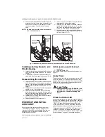
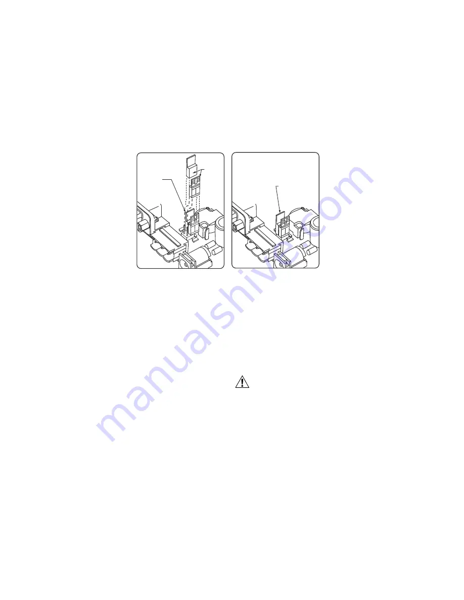
Fig. 8. Install shorting blocks across both sides of jumper block to add RS-485 bias.
Installing shorting blocks to add
RS-485 biasing.
1.
Locate the four jumper pins behind the RS-485 port,
with 2-pin shorting blocks installed on one pin each.
See Fig. 8.
2.
To add biasing, remove and replace both shorting
blocks back onto the jumper pins, as shown in Fig. 8.
Reassembling the controller.
1.
Carefully replace the processor module board onto
the 50-pin connector, with its corner mounting holes
aligned on the four lower standoffs. Press down on
the connector to fully seat the board. See Fig. 7 on
2.
Refasten the four metal hex standoffs, hand tighten-
ing with a 1/4 in. (7 mm) nutdriver.
3.
Replace the shield back onto the unit. To do this,
carefully ease it over the port side first, then spring it
down over the other side. Make sure that its corner
holes align with the metal standoffs below.
4.
Refasten the four Phillips head screws that secure
the shield to the standoffs.
5.
Replace the plastic cover onto the unit.
POWER UP AND INITIAL
CHECKOUT
Ensure power wiring to the controller is ready—see
“Power Wiring” on page 7. See Fig. 3 page 4 for the
location of status LEDs and connectors. See Fig. 4 on
page page 8 for the location of the NPB-PWR-H/U
module’s power connector.
After completing all mounting and wiring, do the following:
Initial power up and checkout.
1.
Apply Power.
2.
Check the Status LED.
Also see the section “About Backup Configurations” on
Apply Power
To apply power, insert the power plug into either the NPB-
PWR-H/U module, or if using a NPB-WPM-US/U wall
adapter, the controller. If using the line-voltage input NPB-
PWR-UN-H/U power supply module, energize the 120–
240Vac circuit wired to the module.
CAUTION
Do not connect both the NPB-WPM-US/U and
NPB-PWR-H/U / NPB-PWR-UN-H/U supplies at
the same time, or equipment damage may
result.
Check the Status LED
When power is applied, the green LED labeled “STATUS”
will light. This indicates that the system is OK, with power
applied. When the controller finishes booting, the yellow
“BEAT” LED should be blinking steady at a 50% duty
cycle, typically at a 1Hz rate. In most cases, this blink
pattern starts about 30 seconds after power is applied.
If after applying power, the STATUS LED goes out, or if
the BEAT LED comes on (steady) and stays lit over 2
minutes, seek technical assistance. See the section “LED
Status Indicators” on page 13, especially “Heartbeat”.
POSITION OF
PRE-INSTALLED
SHORTING BLOCKS
(NO BIASING)
SHORTING BLOCKS
INSTALLED ACROSS
JUMPER PINS
(BIASING ADDED)
SHORTING
BLOCKS
LIFTED
AWAY
M34996


