WEB-300E, WEB-600E/U, CP-300E, CP-600E/U SERIES CONTROLLERS
31-00010—01
14
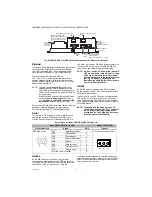
Ethernet Ports
Each Ethernet port has a green LED, labeled on the top
cover “LAN2” (or “SEC”), and “LAN1” (or “PRI”). The LED
indicates activity on that LAN2 (secondary) port or LAN1
(primary) port as follows:
•
Off
— No Ethernet link is made.
•
On
— Ethernet link is present, but no activity on the
LAN.
•
Blinking
— Ethernet link is present with data activity
on the LAN.
Heartbeat
A yellow heartbeat “BEAT” LED is next to the Ethernet
LEDs, also visible on the cover. In normal operation, this
LED blinks at 1 Hz, at 50%/50% on/off duty cycle.
During controller bootup
, this LED blinks at 1 Hz with a
90%/10% on/off duty cycle
on any controller running
WEBs-AX-3.7 update 1 (build 3.7.106) or later. When
bootup completes, the platform daemon is started, and
the normal (50%/50%) duty cycle heartbeat flash pattern
returns.
CAUTION
This same 90%/10% on/off “BEAT” flash
occurs during critical operations, such as any
firmware upgrade (in progress) to the
controller and/or any attached I/O modules. To
be safe, do not remove power from the
controller while its “BEAT” LED flashes with a
90%/10% on/off duty cycle. Wait for the normal
(50%/50%) flash to return before removing
power.
If the “BEAT” LED stays on constantly, does not light, or
blinks very fast—more than 1Hz (once per second), seek
technical support.
Status
The green “STATUS” LED is next to the heartbeat LED,
and is visible on the cover. This LED provide a CPU
machine status check, and should remain lit whenever the
controller is powered. If the status LED does not light
while power is applied, seek technical support.
Serial Ports
LEDs for the two serial ports are located on the
controller’s bottom board, on the opposite side of the RS-
232 and RS-485 ports. Labels “COM1” and “COM2”
correspond to the software configuration of the COM
ports. LEDs show the transmit and receive activity for the
serial ports and optional modem.
NOTE: You must remove the cover to see these
LEDs. See “Removing and Replacing the
• The yellow transmit LED indicates that the controller is
sending data out the serial port over a communications
line to a connected device.
• The green receive LED indicates that the controller is
receiving data from a connected device.
Serial port LEDs provide a fixed on-time when data is
detected on the port. If the receive LED is on constantly,
this indicates a problem with the communications
channel, such as a shorted wire or reversed wiring.
MAINTAINING THE
CONTROLLER
This section provides information on the following topics:
• Cleaning
• NiMH Battery Installation and Maintenance (optional)
• Replacement Parts
• Replacing the Controller Base Assembly
• Returning a Defective Unit
Cleaning
If dust or metal filings are present inside the unit, clean
with vacuum or compressed air. Otherwise, no cleaning
inside the unit is required. Optionally, if the cover
becomes dirty, you can wipe it with a damp cloth and mild
detergent.
NiMH Battery Installation and
Maintenance
• Installing or replacing the optional NiMH battery
• Battery maintenance
• Battery disposal
INSTALLING OR REPLACING THE OPTIONAL NIMH
BATTERY
The optional NiMH battery pack is sold as an assembly,
that is a custom battery pack with an attached cable and
connector plug, mounted on a bracket. To install (or
replace) the battery, you must remove power to the
controller and remove its cover. Then you mount the
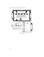
battery assembly on top of the option card area (Fig. 9).


