WEB-600E AND CP-600E NETWORK CONTROLLERS
3
62-0433—01
away such equipment. Instead, these products must enter the
recycling process. To properly dispose of this product, please
take it to a local recycling center.
If a local recycling center cannot be found, please return it to
one of these offices:
MOUNTING
Mount the controller in a location that allows clearance for
wiring, servicing, and module removal.
NOTES: This product is intended for indoor use only.
Depending on installed options, the allowable tem-
perature range varies. See Environmental Require-
ments below.
Avoid mounting the controller in a manner that would
make it difficult to operate the disconnect device. See
Physical Mounting for more details.
Before mounting the controller, install any option
card(s). See “About Option Cards” on page 5. Also
see “RS-485 Biasing” on page 11.
Environmental Requirements
• Do not expose the unit to ambient operating temperatures
outside the range:
— 0°C (32°F) to 60°C (140°F), providing the unit:
• Is
not
powered by the AC line input NPB-PWR-UN-
H module
a
,
and
• The optional NiMH battery pack is
not installed
.
Otherwise, the maximum ambient operating temperature
range is:
— 0°C (32°F) to 50 (122°F).
• Do not expose the unit to humidity outside 5% to 95% non-
condensing (pollution degree 1).
• If mounting inside an enclosure, that enclosure should be
designed to keep the unit within its required operating
range considering a 20-watt dissipation by the controller,
plus dissipation from any other devices installed in the
same enclosure. This is especially important if the
controller is mounted inside an enclosure with other heat
producing equipment.
• Do not mount the unit:
— in an area with excessive moisture, corrosive fumes,
or explosive vapors.
— where vibration or shock is likely to occur.
— in a location subject to electrical noise. This includes
the proximity of large electrical contactors, electrical
machinery, welding equipment, spark igniters, and
variable frequency drives.
Physical Mounting
The following information applies about physically mounting
the unit.
• You can mount the controller in any orientation. It it not
necessary to remove the cover before mounting.
• Mounting on a 35mm wide DIN rail is recommended. The
controller’s unit base has a molded DIN rail slot and locking
clip, as do the power supply modules and both types of I/O
expansion modules. Mounting on a DIN rail ensures
accurate alignment of connectors between all modules.
• If DIN rail mounting is impractical, you can use screws in
mounting tabs on the controller, as well as any end-
connected accessory (NPB-PWR-H, etc.). Tab mounting
dimensions are on the last page of this document.
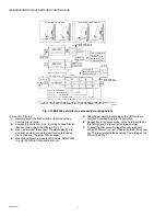
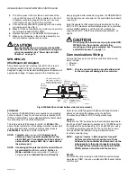
Figure 1 and the following procedure provides step-by-step
DIN rail mounting instructions for the controller.
Tridium Europe Ltd
1, The Grainstore
Brooks Green Road
Coolham, West Sussex
RH13 8GR United Kingdom
Tridium Asia Pacific Pte Ltd
17 Changi Business Park Central 1
Honeywell Building
Singapore 486073
Tridium, Inc.
2256 Dabney Road,
Suite C
Richmond, VA 23230
a
Powering the controller with the wall mount adapter (NPB-
WPM-US) at 60°C (140°F) is supported, however, at 60°C its
output is derated 50%, i.e. 15V at 0.5A (7.5W). No IO mod-
ules are supported.


