WEB-600E AND CP-600E NETWORK CONTROLLERS
62-0433—01
14
PowerMonitorService). Station alarms are generated
whenever primary power is lost, or if the battery is uncharged
or unable to hold a sufficient charge.
NOTE: A NiMH battery characteristic is to lose charge if
not left in charge mode (trickle charge). Leaving
the battery unconnected, or in the unit powered
off will cause the battery to fully discharge in a
matter of weeks. Note that a new NiMH battery
may be partially discharged. Therefore, allow at
least 18 hours for a new battery to charge if it has
not been in a powered unit.
The NiMH battery assembly should be replaced
approximately every three years, or more often if the unit is in
a high temperature environment. For more details, see “NiMH
Battery Installation and Maintenance” on page 14
STATUS LEDS
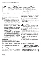
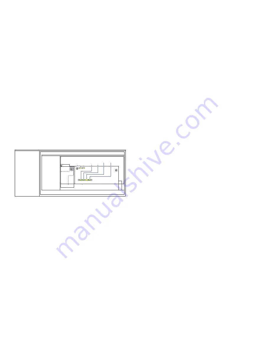
The controller includes several LEDs that can help determine
the status of the unit. They are located in two places: the top
of the controller, visible through the cover, and for serial ports,
on the bottom board (only with cover removed).
Ethernet Ports
Each Ethernet port has a green LED, labeled on the top cover
“LAN2” (or “SEC”), and “LAN1” (or “PRI”). The LED indicates
activity
on that LAN2 (secondary) port or LAN1 (primary) port
as follows:
•
Off
— No Ethernet link is made.
•
On
— Ethernet link is present, but no activity on the LAN.
•
Blinking
— Ethernet link is present with data activity on
the LAN.
Heartbeat
The yellow heartbeat “HBEAT” LED is next to the Ethernet
status LEDs, and is visible on the cover. Under normal
operation, this LED should blink about once per second. If the
heartbeat LED stays on constantly, does not light, or blinks
very fast (more than once per second), contact System
Engineering for technical support.
Status
The green “STATUS” LED is next to the heartbeat LED, and is
visible on the cover. This LED provide a CPU machine status
check, and should remain lit whenever the controller is
powered. If the status LED does not light while power is
applied, contact System Engineering for technical support.
Serial Ports
LEDs for the two serial ports are located on the controller’s
bottom board, on the opposite side of the RS-232 and RS-485
ports. Labels “COM1” and “COM2” correspond to the software
configuration of the COM ports. LEDs show the transmit and
receive activity for the serial ports and optional modem.
NOTE: You must remove the cover to see these LEDs.
See “Removing and Replacing the Cover” on
• The
yellow
transmit LED indicates that the controller is
sending data out the serial port over a communications line
to a connected device.
• The
green
receive LED indicates that the controller is
receiving data from a connected device.
Serial port LEDs provide a fixed on-time when data is
detected on the port. If the receive LED is on constantly, this
indicates a problem with the communications channel, such
as a shorted wire or reversed wiring.
MAINTAINING THE
CONTROLLER
This section provides information on the following topics:
• Cleaning
• NiMH Battery Installation and Maintenance (optional)
• Replacing the Controller Base Assembly
Cleaning
If dust or metal filings are present inside the unit, clean with
vacuum or compressed air. Otherwise, no cleaning inside the
unit is required. Optionally, if the cover becomes dirty, you can
wipe it with a damp cloth and mild detergent.
NiMH Battery Installation and
Maintenance
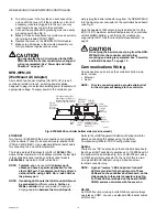
• Installing or replacing the optional NiMH battery
Installing or replacing the
optional NiMH battery
The optional NiMH battery pack is sold as an assembly, that is
a custom battery pack with an attached cable and connector
plug, mounted on a bracket. To install (or replace) the battery,
you must remove power to the controller and remove its cover.
Then you mount the battery assembly on top of the option
card area (Fig. 9).
From left-to-right these LEDs include:
Visible on
cover:
• Ethernet
• Status
Bottom
board only:
• Serial
FROM LEFT-TO-RIGHT THESE LEDS INCLUDE:
COM 2
SERIAL PORT LEDS ON BOTTOM STATUS LEDS (VISIBLE WITH COVER ON):
BOARD, REMOVE COVER TO SEE:
BEAT STATUS
COM 1
VISIBLE ON
COVER:
• ETHERNET
PORTS
• HEARTBEAT
• STATUS
BOTTOM
BOARD ONLY:
• SERIAL
PORTS
MCR33925
LAN2
(SEC)
LAN1
(PRI)


