WEB-600E AND CP-600E NETWORK CONTROLLERS
62-0433—01
16
REPLACEMENT PARTS
Servicing the WEB-600E controller may call for replacement
parts. There are three categories of parts:
Non-replaceable Parts
Other than the parts listed in the replacement parts sections,
there are no serviceable components on the base assembly.
Memory
Any addition, modification, or replacement of memory
components requires software configuration and is not a field
upgrade. For additional information on modifying the memory
capacity of the controller, consult your regional Tridium office.
FUSE
The controller contains a non-user replaceable fuse, soldered
on the circuit board. This fuse provides protection from
internal shorts or connection to incorrect power supplies. If the
fuse circuitry is suspect, contact your regional Tridium office
for technical support. See “Returning a Defective Unit” on
Standard Replacement Parts
Standard replacement parts are listed in Table 4, and can be
ordered from stock without restriction. Standard replacement
parts cannot be returned for credit and should be disposed of
in an appropriate manner.
New Replacement Unit
To replace an entire unit, order and install a
new
WEB-600E
controller. If the faulty controller is
still in warranty
, you can
receive credit by returning it. Be sure to contact the vendor for
a return authorization (RA) number before shipping an item for
return credit. See “Returning a Defective Unit” on page 17, for
more details.
NOTE: Before ordering a new controller, it is strongly
recommended that you contact your normal
technical support resource to eliminate the pos-
sibility of a software issue or mis-configuration
problem.
Replacing the Controller Base
Assembly
NOTE: Before handling circuit boards, discharge any
accumulated static by touching a nearby earth
ground. For details, see “Static Discharge Pre-
To replace a WEB-600E with a new replacement unit, proceed
as follows:
1.
If possible, use the appropriate WEBs-AX software tool
to back up the controller’s configuration to your PC.
2.
Remove power to the controller. The unit should power
down automatically. Wait for all LEDs to remain off.
NOTE: If IO accessory modules are installed, and any I/
O points have voltage, turn the devices off or dis-
connect power to them.
3.
Note positions of all communications and other wiring
cables going to the controller, as well as installed acces-
sory modules (if they must be removed). If necessary,
label connectors and accessory modules to avoid mis-
connection later, after the controller is replaced.
4.
Unplug all Ethernet, serial, LON, modem, and I/O con-
nectors from the controller.
5.
If IO accessory modules are installed:
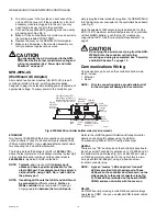
— If DIN rail mounting with DIN end-clips was used, you
may be able to remove the DIN rail end clip that
secures the WEB-600E end of the assembly, and then
slide the controller away from the rest of the assembly.
Then you can remove the controller from the DIN rail
(see Fig. 2), leaving the mounting and wiring of IO
modules untouched.
In this case, after removing the controller from the DIN
rail, go to 6.
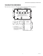
— If tab (screw) mounting was used
instead
of DIN rail
mounting, or if a combination of DIN mounting and tab
screws was used (into the controller’s “accessory side”
tab holes, see last page), you will need to remove
accessory modules
first
, before removing the control-
ler. In this case:
a. Making a careful note of all wiring terminations,
unplug the I/O connector plugs and earth ground
wires from the installed IO modules.
b. Remove the installed accessory modules, starting
with the end module.
c. c Remove any screws fastening the controller, and
remove it (see Fig. 1).
6.
Remove the cover of the old unit. See “Removing and
Replacing the Cover” on page 5. Note the position of
installed option cards, if any. You must transfer them to
the replacement controller.
7.
Remove any option cards from the old controller and
install them into the replacement WEB-600E controller,
if applicable. See “Installing an Option Card” on page 7
for more details.
8.
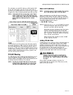
Check the RS-485 biasing jumpers on the existing unit,
and duplicate on the replacement unit (see “Installing an
9.
Mount the replacement controller as it was previously,
using the same DIN rail location and/or screws.
10.
Reconnect/remount any removed accessory modules,
being careful to replace in the same order, using the
same DIN rail location and/or screws. Secure all mod-
ules as done previously.
Table 4. Standard replacement parts
for a WEB-600E controller.
Part Number
Description
WEBs-AX
Optional NiMH Battery Pack—see “NiMH
Battery Installation and Maintenance” on
H10027
RS-485 connector plug, 3-position.

