WEB-600E AND CP-600E NETWORK CONTROLLERS
62-0433—01
4
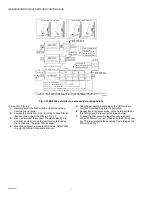
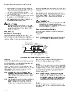
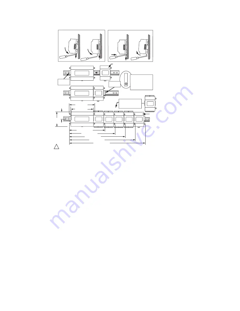
Fig. 1. WEB-600E controller and accessory mounting details.
To mount on DIN rail:
1.
Securely install the DIN rail with at least two screws,
near the two rail ends.
2.
Position the controller on the rail, tilting to hook DIN rail
tabs over one edge of the DIN rail (Fig. 1).
3.
Use a screwdriver to pry down the plastic locking clip,
and push down and in on the unit, forcing the locking
clip to snap over the other DIN rail edge.
4.
Mount any accessory module (I/O module, NPB-PWR-
H) onto the DIN rail in the same manner.
5.
Slide the accessory module along the DIN rail to con-
nect its 20-position plug into the controller.
6.
Repeat this for all accessories, until all are mounted on
the DIN rail and firmly connected to each other.
7.
To keep the final assembly together, secure at both
ends with DIN rail
end-clips
provided by the DIN rail ven-
dor. This also prevents the assembly from sliding on the
DIN rail. See Fig. 1.
WEB-600E
IO-16-H
MOUNTING ON DIN RAIL
DIN RAIL
END CLIP
DIN RAIL
END CLIP
INSTALL DIN RAIL
END CLIP
(STOP CLIP) AT
BOTH ENDS OF
FINAL ASSEMBLY.
UP TO FOUR
IO-16-H MODULES
ARE SUPPORTED.
7-1/8 (181)
6-3/8 (162)
2-3/64 (52)
4-7/64
(104)
10-23/64 (263)
13-37/64 (345)
16-13/16 (427)
M33914
REMOVING FROM DIN RAIL
NPB-PWR-H OR
NPB-PWR-UN-H
WEB-600E
NPB-PWR-H or
NPB-PWR-UN-H
20-3/64 (509)
23-17/64 (591)
IF INSTALLING IO MODULES AND USING THE NPB-PWR-H OR NPB-PWR-UN-H POWER SUPPLY
MODULE, THE POWER SUPPLY MODULE INSTALLS AT THE
END
OF THE CHAIN.
1
IO-16-H
WEB-600E


