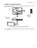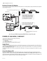
WEB-700 WEB-700-O CP-700
95-7776—01
14
WEB-700; WEB-700-O; CP-700
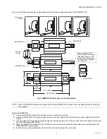
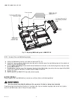
Fig. 6. WEB/CP-700 option card and shield removal, DDR-2 SODIMM module
Replacing or upgrading DDR-2 RAM Module in a WEB/CP-700.
1. Remove power
from the WEB/CP-700, including disconnection of any external battery.
2.
Remove the controller from any mounting (see NOTE: above).
3.
Remove the cover. See Removing and Replacing the Cover, page 10.
4.
Remove any option card slot installed in slot 1, retaining both screws.
If no option card is in slot 1, remove the blanking plate and screws.
5.
Remove and retain the other 3 screws in the remaining tabs of the shield.
6.
Lift the shield/NiMH battery assembly off the main board. You can leave the battery connected to the main board.
7.
Press apart the end clips on the RAM socket to release tension and allow the SODIMM memory module to angle upwards.
8.
Pull the SODIMM module out from the socket, noting the keyed slot on the module’s edge connectors (side nearest the
DB-9 connector).
9.
Insert the replacement SODIMM module into the socket, at same angle and keyed slot oriented the same way. Fully seat
the module into the socket.
10.
Push down on the back of the SODIMM module, until socket end clips snap in place. Ensure the module is installed cor-
rectly. Only a small, even area of its gold edge connectors should be visible where they enter the socket.
11.
Reinsert any option card removed from slot 1, being careful to align pins correctly such that mounting holes align with the
standoffs. If no option card was installed, put the blanking end plate into position.
12.
Place the shield/NiMH battery assembly back onto the controller’s standoffs, lining up the screw holes on the 4 tabs of the
shield.
13.
Place a screw into the hole of each of the 4 shield tabs, loosely threading each one at first, then hand tightening them using
a screwdriver. Refasten any remaining screws for option cards.
14.
Replace the cover, being careful of the LED ribbon cable connecting it to the controller’s main board.
15.
Remount the controller as previously, if applicable.
16.
Restore power, including re-connection of any external battery.
Option Slot 1
Option Slot 2
End Clip on RAM SODIMM Socket
RAM SODIMM socket
DDR-2 SODIMM memory module
Option card or
blanking plate in
Slot 1 must be
removed before
shield can be
removed.
Shield Tab
Option card in Slot 2 must be
installed
under
the shield tab.
Shield with NiMH
battery assembly
Shield Tab


