DB7110U UNIVERSAL HEAT PUMP DEFROST CONTROLLER
34-00032—01
4
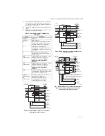
Fig. 8. Wiring diagram for simple timer applications.
CONFIGURATION
1.
Connect power.
2.
On power up the display will briefly flash the
software version of the DB7110U and then begin
cycling between the normal operating screens
showing the current mode and the values of the
two temperature sensors. Note that there is brief
startup delay following power up where com-
pressor operation is prohibited.
Fig. 9.
The displayed coil and air temperature readings
can be very useful for optimizing and trouble-
shooting defrost performance.
3.
There are several configurable options to opti-
mize defrost performance. See “User Interface”
on page 7 for a detailed description of each
parameter/screen. Press the
select (o)
button
advance through the various screens and
and
buttons to adjust the various parameters.
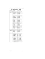
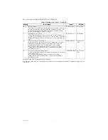
Table 4 below describes each parameter.
CHECKOUT
1.
After the startup delay has expired, generate a
request for heat by shorting R to Y (and R to O if
configured as a “B” system, reversing valve ener-
gized in heating mode).
2.
Verify the compressor, fan, and reversing valve (if
applicable) are energized.
3.
Press and hold the
button until “tESt” appears
on the display as shown below.
Fig. 10.
4.
Verify the unit enters defrost mode
Fig. 11.
The reversing valve will change states and the
aux heat will be energized. A few moments later
the fan will be turned off. If Reversing Delay is
enabled, the compressor will be turned off for
the selected time, and then turn back on to
reduce noise.
The DB7110U will remain in defrost for at least
one minute. After one minute has elapsed, the
DB7110U will exit defrost after the coil tempera-
ture has risen above the termination
temperature or after the selected defrost time,
whichever comes first.
Test mode can be terminated at any time by
pressing and holding the
button again.
LPC
HPC
CONTACTOR
AUX
REVERSING
VALVE
FAN-IN
FAN-OUT
R
C
O/B
W
Y
COIL
SENSOR
INDOOR
EQUIPMENT
OUTDOOR
EQUIPMENT
DB7110U
L1
L2
COMPR
RV
FAN
IF THE PRESSURE
SWITCH(ES) ARE IN SERIES
WITH THE CONTACTOR,
JUMPER THE ONBOARD
CONNECTIONS.
DO NOT BYPASS ANY
PROTECTIVE PRESSURE
SWITCHES.
AIR
COIL
HIGH
PRESSURE
SWITCH
LOW
PRESSURE
SWITCH
WHEN THE COMPRESSOR CONTACTOR IS POWERED DIRECTLY
FROM THE Y TERMINAL, SET THE REVERSING DELAY AND SHORT
CYCLE DELAY TO 0.
M37759
M37640
CURRENT MODE OF OPERATION
OFF, HEAT, COOL, DELAY, ETC.
OUTDOOR COIL TEMPERATURE
DEGREES FAHRENHEIT
OUTDOOR AIR TEMPERATURE
DEGREES FAHRENHEIT
M37641
M37642
de Fr

