background image

DB7110U UNIVERSAL HEAT PUMP DEFROST CONTROLLER

7

34-00032—01

USER INTERFACE

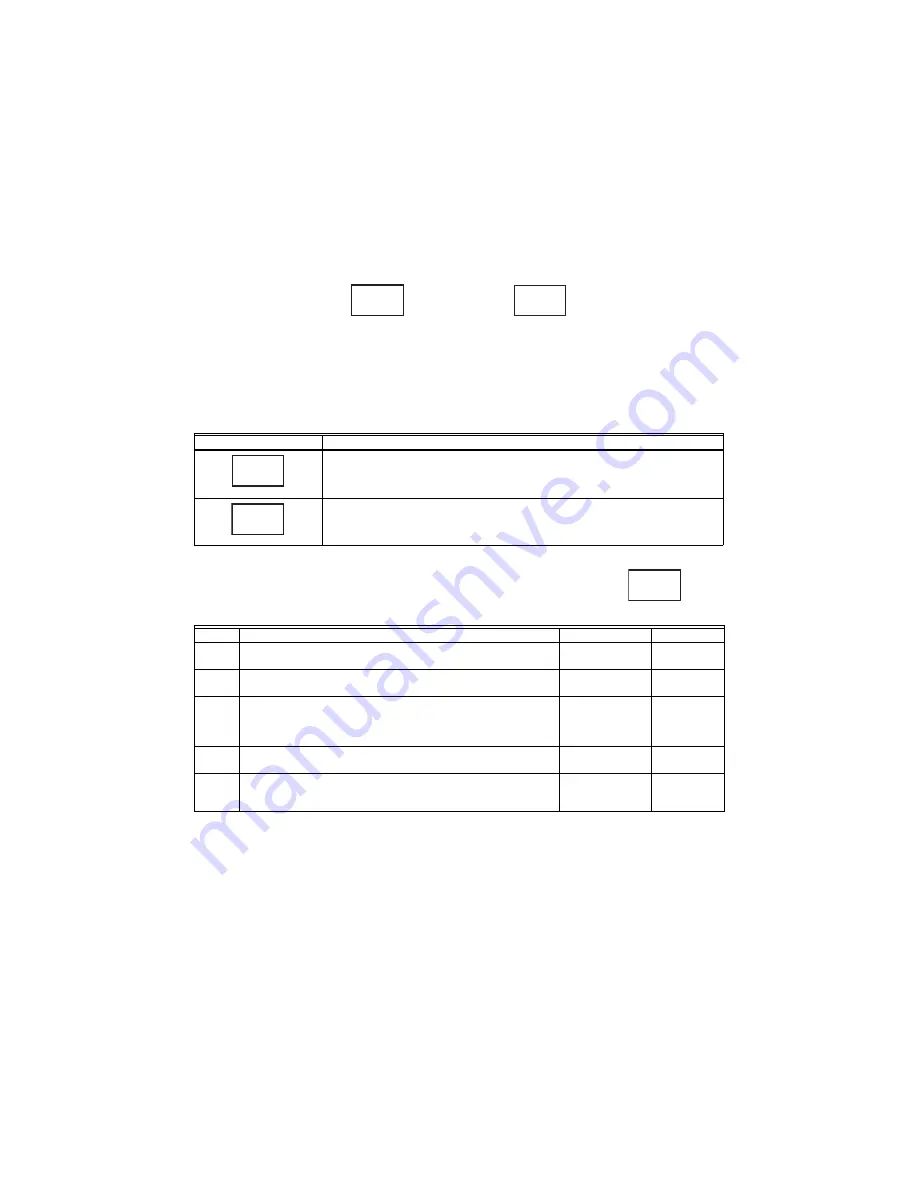
The user interface consists of three buttons, two LED’s, and 4 7-segment digits. The two left digits generally 
represent the category of what is being displayed while the two right digits represent the value or setting of the 
category. The exception is in the event a value requires 3 digits such as a temperature higher than 99F as shown 
below with two “termination temperature” values of 90F and 100F.

Fig. 12. Two example values of configuration option 2 (Termination Temperature).

The “o” button advances to the next screen while the 

 and 

 buttons are used to adjust the value of each 

parameter.

Note that after one hour without a button press, the 7-segment display will turn off to save power. A button must 
be pressed to turn the display on again.

Table 3. Status Screens.

The configuration screens are numbered parameters where numbered parameter has a selectable value 
according to the table below.

For example, would represent Parameter 1 (Defrost Enable Temperature) set to 35 (degF).   

Display

Description

Current Fault(s) Present.
Right digits blank if there is no fault.

 and 

 to scroll through active faults.

Fault History

 and 

 to scroll through history.

Press and hold 

 for more than two seconds to clear all inactive faults.

Table 4. Configuration Screens. 

Display

Description

Range

Default

1

Defrost Enable Temperature 
Coil temperature where defrost functionality is active. 

30degF-36degF

35degF

2

Termination Temperature.
Coil temperature where defrost is terminated.

70degF-100degF 70degF

3

Defrost Cycle Time
Time the coil temperature is below the Defrost Enable 
Temperature before a defrost is triggered if in timed mode 
(no outdoor air sensor present).

30-120 minutes

30 minutes

4

Short  Cycle  Delay  Time 
Minimum off time between compressor cycles.

0-5 minutes

3 minutes

5

Reversing Valve System Type
O = reversing valve energized in cool.
B = reversing valve energized in heat.

O or B

O

90

1


00

M37659

2

2

4


F

M37660

H   11 

F

M37661

1 35

M37662

Summary of Contents for DB7110U

Page 1: ...bleshooting Fig 1 DB7110U1000 SPECIFICATIONS Electrical Ratings Input Voltage 24VAC 60Hz Max Input Current 200mA Compressor Contactor 1A 24VAC Outdoor Fan 1 2HP motor 5A full load 30A locked rotor 240VAC Aux Heat 1A 24VAC Reversing Valve 1A 24VAC All outputs rated for 100 000 operations All terminals except FAN IN and FAN OUT are NEC Class 2 low voltage Environmental Ratings Operating Temperature ...

Page 2: ...ess place the new coil sensor on the coil loop nearest the expan sion valve where refrigerant is entering the coil during the heating mode This location gives the largest temperature difference between the air 4 Ensure the coil sensor is clamped tightly to the coil It may be desirable to add insulation to the sensor to yield more accurate readings although this is generally not needed Fig 3 Coil S...

Page 3: ...must be shorted for compressor operation Never bypass protective pressure switches LPC 2 Terminals High pressure cutout switch these terminals must be shorted for compressor operation Never bypass protective pressure switches AUX Output to auxiliary emergency heat energized during a defrost cycle or when requested by W input COMPR 2 Terminals Output to compressor contactor energized by Y request R...

Page 4: ... energized 3 Press and hold the button until tESt appears on the display as shown below Fig 10 4 Verify the unit enters defrost mode Fig 11 The reversing valve will change states and the aux heat will be energized A few moments later the fan will be turned off If Reversing Delay is enabled the compressor will be turned off for the selected time and then turn back on to reduce noise The DB7110U wil...

Page 5: ...CM316 ICM317 ICM318 ICM319 ICM320 ICM321 ICM322 ICM323 W1001 4 ICP 1052757 1069364 Interthem 6208800 Lennox 100269 01 100269 02 100269 04 100269 05 11K7101 1507N170027 29M0101 29M0201 30W87 33G9501 34M6301 46K67 56M3701 68I2901 68J8401 78H6801 84W8801 86G1601 97M81 LB 101263A LB 101263B 11K71 97M8101 30W8701 34M63 29M01 56M37 HPXB15 68I84 68I29 78H68 Nordyne 620880 621301A 621579B 621579C 624519A ...

Page 6: ...T02935 CNT03715 CNT03716 CNT04362 CNT04363 CNT04364 CNT04366 CNT04368 CNT04695 CNT05001 CNT05008 CNT05009 CNT05010 CNT05482 CNT05875 CNT1108 CNT01693 Weatherking 840 4 5548 White Rodgers 840 4 5548 47D40 801 47D43 101 47D43 111 47D43 11102 47D43 811 90 621 47D01U 843 York 031 00872 001 031 00872 002 031 00872 002 031 00872 701 031 00872 702 031 00872 703 031 01222 000 031 01251 000 031 01268 000 0...

Page 7: ...mbered parameter has a selectable value according to the table below For example would represent Parameter 1 Defrost Enable Temperature set to 35 degF Display Description Current Fault s Present Right digits blank if there is no fault and to scroll through active faults Fault History and to scroll through history Press and hold for more than two seconds to clear all inactive faults Table 4 Configu...

Page 8: ... Termination Temperature but a defrost cycle should never last longer than this time 8 14 minutes 14 minutes 8 Aux Heat Lockout Temperature W requests will be ignored if the outdoor temperature is higher than this temperature The Aux heat output will still function normally during a defrost cycle regardless of this setting Do not set this temperature below the Compressor Lockout Temperature or the...

Page 9: ... to run Never bypass protective pressure switches Check coil sensor the system will not run without a coil sensor Control displays DLY The system is in a startup delay due to short cycle protection powerup or low voltage Wait for the delay to expire Compressor does not stop when the call for heat or cool ends Observe display for current operational mode Control displays current mode OFF HEAT or CO...

Page 10: ...are correct Increase the Termination Temperature to allow the coil to get hotter before a defrost cycle is terminated Increase the Maximum Defrost Time to allow a defrost cycle to run longer System defrosts too much Observe defrost cycle Defrost triggers too frequently even with little or no ice buildup Verify sensor placement and readings are correct Decrease the Enable Temperature to force the c...

Page 11: ...h Pressure Cutout is currently open Investigate refrigerant charge Check indoor coil for blockage Check outdoor coil for blockage 8 Low Pressure Cutout is currently open Investigate refrigerant charge 9 Coil Sensor Open Circuited Check the sensor hasn t become unplugged Check sensor wiring Replace sensor 10 Coil Sensor Shorted Check for pinched wires Replace sensor 11 Air Sensor Open Circuited Che...

Page 12: ... Resideo Technologies Inc All rights reserved The Honeywell Home trademark is used under license from Honeywell International Inc www resideo com Resideo Inc 1985 Douglas Drive North Golden Valley MN 55422 34 00032 01 M S 12 18 Printed in United States ...

Reviews: