ENS7003R16 KO65 2013
2
3. SPECIFICATIONS
Table 1: Model Selection Guide
Model
Description / Application
Supply voltage
DBC2000E10xx (*) Standard model
115V or 230V
(see detailed specs on page 4)
DBC2000E20xx (*) Enhanced model
DBC2000E30xx (*) Ultimate model (future release)
The Enhanced Model includes a Valve Proofing System.
The Ultimate model includes both remote bus communication and a Valve Proofing System.
(*) xx depends on supply voltage and timings. For exact model number, please refer to product selection matrix ot
technical catalogue on http://products.ecc.emea.honeywell.com/europe.
Table 2: Sequence timing Standard Model
Waiting for
AFS
Waiting for
HF
Pre-
purge
Ignition
Pilot-
only
Main
trial
Main
stabilization
Post-
purge
Flame
failure
response
300s (max) 300s (max)
35s
1)
3s
5s
3s
2)
4s
2)
15s
3)
1s (max)
1)
Default pre-purge time is 35s. Other timings on request, by OS number selection.
2)
Set to 0s. when DBI function is enabled (terminal 22 jumpered to line voltage).
3)
Set to 0s. when “no post-purge” feature is enabled (terminal 12 jumpered to line voltage).
Sequence at flame failure: immediate lock out
Table 2a: Sequence timing Enhanced and Ultimate Models
Waiting for
AFS
Waiting for
HF
Pre-
purge
Ignition
Pilot-
only
Main
trial
Main
stabilization
Post-
purge
Flame
failure
response
300s (max) 300s (max)
35s
1)
3s
5s
3s
2)
4s
2)
15s
3)
1s (max)
1)
Default pre-purge time is 35s. Other timings on request, by OS number selection.
2)
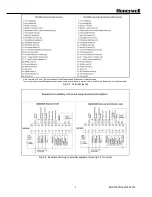
Set to 0s. when DBI function is enabled using the DIP-switches on the front, at the bottom left corner (Fig 4-5).
3)
Set to 0s. when “no post-purge” feature is enabled using the DIP-switches on the front, at the bottom left corner (Fig 4-5).
Sequence at flame failure: immediate lock out
Table 3: Contact ratings
Terminal
Load
Contact rating
3
Blower / Fan
3A
@ cosφ=0
.6
4
Ignition transformer
3A @ cosφ=0.6
5
Intermittent pilot or main (DBI) valves
3A @ cosφ=0.6
6
Interrupted pilot
3A @ cosφ=0.6
7
Main (PI) valves
3A @ cosφ=0.6
12
Main (PI) valve 2 (ENH/ULT models only)
3A @ cosφ=0.6
8, 9, 10, 11
Control motor
0.5A
@ cosφ=0
.6
21
Alarm
0.5A @ cosφ=0.6
Total load (based on set): Max 8A (Internal Fuse : 10A)
Total load (based on terminal 4,5,6,7): Max 5A (Internal Fuse : 6.3A)
Summary of Contents for DBC2000E10 Series
Page 13: ...ENS7003R16 KO65 2013 13 ...
Page 15: ...ENS7003R16 KO65 2013 15 ...
Page 16: ...ENS7003R16 KO65 2013 16 ...
Page 17: ...ENS7003R16 KO65 2013 17 ...
Page 18: ...ENS7003R16 KO65 2013 18 ...
Page 19: ...ENS7003R16 KO65 2013 19 ...
Page 20: ...ENS7003R16 KO65 2013 20 ...
Page 21: ...ENS7003R16 KO65 2013 21 ...
Page 27: ...ENS7003R16 KO65 2013 27 ...
Page 28: ...ENS7003R16 KO65 2013 28 ...
Page 29: ...ENS7003R16 KO65 2013 29 ...
Page 30: ...ENS7003R16 KO65 2013 30 ...
Page 31: ...ENS7003R16 KO65 2013 31 ...
Page 32: ...ENS7003R16 KO65 2013 32 ...
Page 33: ...ENS7003R16 KO65 2013 33 ...
Page 34: ...ENS7003R16 KO65 2013 34 ...


