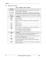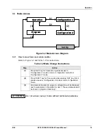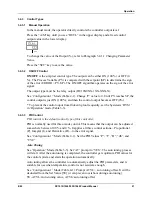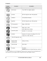
Configuration
26
DC1010/1020/1030/1040 Product Manual
8/05
4.2.1 Configuration
2
To access ‘Configuration 2’ mode, press the ‘
SHIFT
’ key for 5 seconds WHILE pressing
‘SET’ key FIRST when in ‘Operation’ or ‘Configuration 1’ mode.
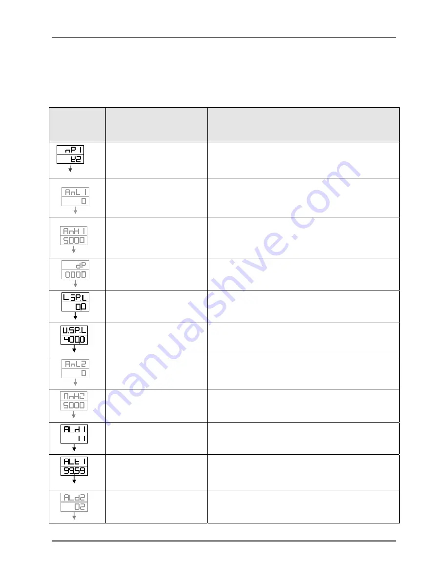
Table 4-2 Configuration 2 Mode
Displays
Default Value
shown except for
examples
Parameter
Description
SET
I
SET
I
Input 1 (INP1)
Selection (Code)
Defines the Input type and Input range
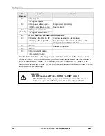
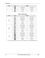
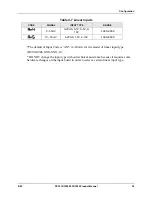
* Refer to Table 4-5, Table 4-6, and Table 4-7 for Input
Codes
example
SET
SET
Input 1 (INP1)
Lower Limit of Linear input
Used during calibration of linear input
* DO NOT change this value without technical
assistance
example
SET
SET
Input 1 (INP1)
Upper Limit of Linear input
Used during calibration of linear input
* DO NOT change this value without technical
assistance
SET
SET
Decimal Point
Used to set the position of the decimal point.
Available for Linear Input only
SET
SET
Lower Setpoint Limit
For Example: Linear Input = 4-20mA, when 4mA(0%),
set the value for the lower limit
SET
SET
SET
SET
Upper Setpoint Limit
For Example: Linear Input = 4-20mA, when
20mA(100%), set the value for the upper limit
SET
SET
Input 2 (INP2)
Lower Limit of Linear input
Used during calibration of linear input
* DO NOT change this value without technical
assistance
SET
SET
Input 2 (INP2)
Upper Limit of Linear input
Used during calibration of linear input
* DO NOT change this value without technical
assistance
SET
SET
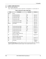
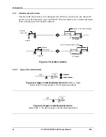
Alarm Code for Alarm 1
* Refer to Table 4-3 for Alarm Codes.
SET
SET
Time set for Alarm 1
* Range: 0-99 min, 59 seconds
0= flickering alarm, 99:59= continual alarm
Other = Time delay for alarm
SET
SET
Alarm Code for Alarm 2
* Refer to Table 4-3 for Alarm Codes.
Summary of Contents for DC1000 SERIES
Page 48: ...Configuration 40 DC1010 1020 1030 1040 Product Manual 8 05 ...
Page 59: ......

