Installation
6
UDC3300 Basic Model: DC330B User Manual
5/00
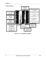
Composite Wiring
1
2
3
4
5
6
7
8
9
L1
L2/N
22
23
24
Auxiliary Output
Terminals
See Figure 2-13
Outputs and Alarms
Terminals
• Time Proportional Output
See Figures 2-6, 2-7, 2-8,
2-9
• Current Output/Universal
Output
See Figures 2-10, 2-11
• Position Proportional
Output
See Figure 2-12
For Control and Alarm Relay
Contact information, See
Tables 2-3 and 2-4.
Digital Inputs
Terminals
See Figure 2-14
AC Line Voltage
Terminals
See Figure 2-4
Input #2
Terminals
See Figure 2-5
Input #1
Terminals
See Figure 2-5
10
11
12
13
14
15
16
17
Communications
Terminals
See Figure 2-15
Transmitter Power for
4-20 mA 2-wire
Transmitters
• Using Alarm 2 Output
See Figure 2-16
• Using Auxiliary Output
See Figure 2-17
I/O shield ground
(Do not use for
Communications shield)
25
26
27
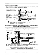
Figure 2-3 Composite Wiring Diagram
Summary of Contents for DC3300
Page 1: ...Sensing and Control UDC3300 Basic Model DC330B User Manual 51 52 25 78 5 00 ...
Page 26: ...Installation 18 UDC3300 Basic Model DC330B User Manual 5 00 ...
Page 70: ...Setpoint Rate Ramp Soak Program Operation 62 UDC3300 Basic Model DC330B User Manual 5 00 ...
Page 72: ...Environmental and Operating Conditions 64 UDC3300 Basic Model DC330B User Manual 5 00 ...
Page 74: ...Model Selection Guide 66 UDC3300 Basic Model DC330B User Manual 5 00 ...
Page 80: ...Position Proportional Calibration 72 UDC3300 Basic Model DC330B User Manual 5 00 ...
Page 82: ...Input Ranges 74 UDC3300 Basic Model DC330B User Manual 5 00 ...
Page 83: ......


