background image


    Global Technical Assistance Center 


Page 4  


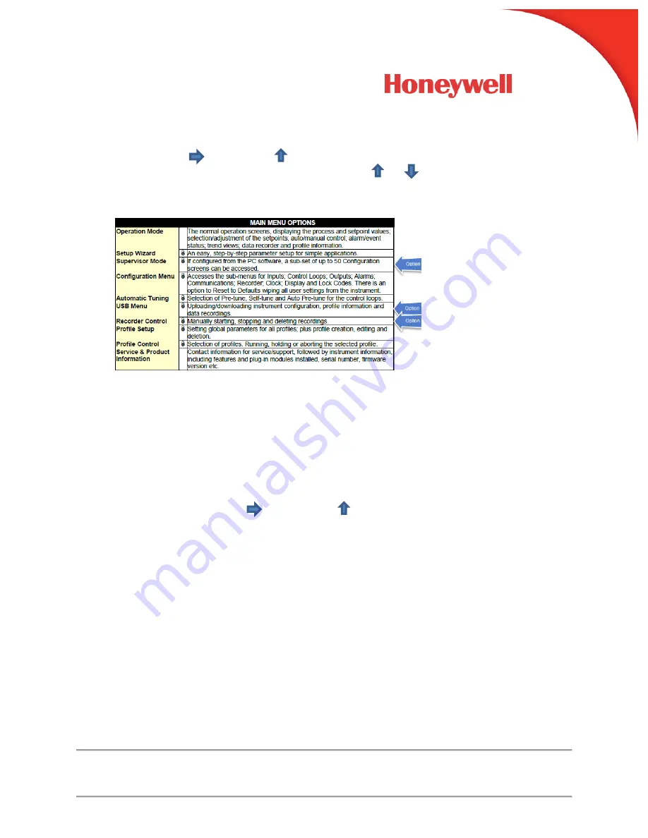
5.  Main Menu Access 

Holding down       and pressing     from Operation Mode and most other screens will 
cause the unit to enter the Main Menu. Each time       or      is pressed, the instrument 
moves to the next menu level above. Sub-menu levels will require this sequence to be 
pressed more than once in order to reach the Main Menu.


The factory default unlock code is 10 for all modes 


6.  Setup Wizard 

– Section 8.3, Page 42 

An easy Setup Wizard runs automatically at first ever power-up. Follow the Wizard to 
setup parameters required for basic applications. The parameters covered by the Setup 
Wizard are marked with a 

in the following sections covering the configuration mode 

sub-menus. Once completed, the Setup Wizard exits to Operation Mode. Experts or 
users with more complex applications can select the parameters they wish to set-up 
directly from the Configuration Menus bypassing the Wizard. 


7.  Configuration 

– Section 8.5, Page 45 

Use Main Menu Access above to enter into Configuration Mode.  

The factory default unlock 

code is 10. Holding down       and pressing      toggle you back to the previous screen.


a.  Input Configuration 

i.  Input 1, Page 46 

ii.  Input 2, Page 47 

b.  Auxiliary Input A, Page 48 
c.  Digital Input. Page 49 
d.  Control Configuration 

i.  Control Loop 1, Page 48 

ii.  Control Loop 2, Page 53 

e.  Output n Configuration, Page 56 
f.  Alarm n Configuration, Page 57 
g.  Communication, Page 58 
h.  Data Recorder, Page 59 
i. 

Clock, Page 61 

j. 

Display, Page 62 

k.  Lock Codes, page 63 
l. 

Reset to Defaults, Page 63 


Summary of Contents for DCP 250

Page 1: ...Up Guide Question This guide along with manual 57 77 25 18 can be used to configure the DCP250 Answer Use the below information to install wire and configure the DCP 250 1 Installation Section 2 2 Page 2 2 Wiring Section 4 5 Page 13 to 28 3 Keypad Navigation Section 5 5 Page 30 ...

Page 2: ...damental questions If fitted how will the 2nd input be used One loop only if the 2nd input not fitted or not used in this application Two independent control loops see page 49 Valve feedback for loop 1 see page 87 A redundant backup for the 1st input see page 85 Cascaded with the first control loop see page 80 A reference input for ratio control see page 83 How will the instrument physically contr...

Page 3: ... see page 99 Serial Communications see page 111 USB Interface see page 98 One Loop Two Loop Cascade and Ratio CAUTION Configuration commissioning must be completed before proceeding to Operation Mode It is the responsibility of the installing engineer to ensure that the configuration is safe ...

Page 4: ...owing sections covering the configuration mode sub menus Once completed the Setup Wizard exits to Operation Mode Experts or users with more complex applications can select the parameters they wish to set up directly from the Configuration Menus bypassing the Wizard 7 Configuration Section 8 5 Page 45 Use Main Menu Access above to enter into Configuration Mode The factory default unlock code is 10 ...

Page 5: ...pears Adjust Main Setpoint using the Up and Down keys ii Automatic Tuning Section 8 11 Page 70 The automatic tune menu is used to engage pre tune and or self tune to assist setting up proportional bands and the integral and derivative time values used by the control loops Pre tune can be used to set PID parameters approximately Self tune Pre tune needs to be run first may then be used to optimize ...

Page 6: ...un Pre Tune on Set 1 now Select Yes to start the tuning process Once Yes is selected a Status screen will appear with the Tuning status When Stopped appear on the lower half of the screen Pre Tune is finished Press enter to proceed Engage Self Tune If Yes is elected the Self Tune feature will be active and the Tune Led is lite continuously Auto Pre Tune at Power Up Recommend None DCP cycles back t...

Page 7: ...ect the Profiler Setup Menu Enter 10 as the unlock code Press to enter Profile Setup Mode b Navigating the Profiler Setup Menu Press to move forward or to move backward through the screens Press or to select or change a value Holding down or for more than 1 second skips immediately to the next previous screen accepting all values as shown Hold down the and press to return to the Main Menu 10 Profi...

Page 8: ... Day and Time trigger is selected this is the Days the Profile will run Profile Start Delay time If After Delay Start trigger is selected this is the time in Hours and Minutes the Profile will run after a start request Control Outputs off Caution this will stop all control Restart Profile from the beginning Maintain Last Profile Setpoint Use Controller Setpoint Continue Profile from where it was w...

Page 9: ...te Profile Repeat Segment Then End Repeat a sequence of joined Profiles The Sepoint Value to be reached by Loop 1 at the end of the segment Loop 2 Target Setpoint The Sepoint Value to be reached by Loop 2 at the end of the segment Rate of Change to Target Setpoint 001 to 9999 9 Units Hour Segment Dwell Time Time to stay at Current Setpoint hh mm ss Number of Loops If the Segment type is Loop enter...

Page 10: ...oint Hold if Auto Hold Band value is exceeded Band Hold if Auto Hold Band value is exceeded either above or below Loop 2 Auto Hold Band Value Two Loop Option Value beyond the Profile is held based on Auto Hold Type Operator Digital No Auto Hold Time of Day Hold if Auto Hold Band value is exceeded Time of day when a Hold Segment will release if the Release Type is Time of Day Number of Time the ent...

Page 11: ...u changes after 1 Profile is added Choose Profile Allows you to edit any Parameter in the Segment Data See Page 9 10 Choose Profile Pick the position to add the segment from the list Choose Profile Pick the Segment number you wish to delete Choose Profile Delete the Profile Name from the list Choose Profile Caution This will delete all Profiles from device 11 Profile operation a Go to Profile Cont...

Page 12: ...ofile Press or to Select Profile Press to enter c Run Profile Press until the Profile Control Screen appears d Confirm Profile Select Yes e Profile starts and can be monitored on the profile screen Continually press the enter key to Show the profile screen ...

Page 13: ...Running Hold Abort or Jump while running the Program is accessed by going to the profile Control and selecting the desired option If a profile is running the choices are Do Nothing Abort Profile end immediately Jump to Next Segment Hold Profile or Release Hold ...

Page 14: ...n 5 seconds as the start up splash screen appears The Lock Code Configuration menu is displayed Press to move forward or to move backwards through the screen elements Make note of the codes or press or to change their values if required Hold down and press to return to the Main Menu Scrolling Help Text is shown at the bottom of the screens to aid navigation ...

Page 15: ... Open Collector Module Slot 1 51453391 503 TRIAC Open Collector Module Slot 2 3 51453391 508 Linear mA Vdc Module Slot 1 51453391 504 Dual Relay Module Slot 2 3 51453391 510 Dual SSR Output Module Slot 2 3 51453391 519 24V Transmitter Power Supply Module Slot 2 3 51453391 511 RS485 Communication Slot A 51453391 512 Ethernet Communication Slot A 51453391 521 Digital Input Module Slot A 51453391 513...

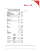
Page 16: ...Global Technical Assistance Center Page 16 14 Model Selection Guide ...

Reviews: