background image

Chapter 8. PROGRAM SETUP

8-9

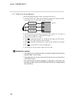
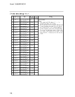
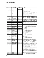
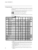
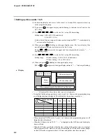
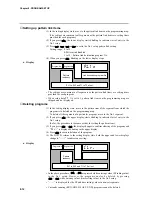
Setting up PID set No. items

(1) In the setting display state, move to the PID set No. items of the segment to be set up

on the programming map.

(2) If you press

ENT

, the lower display starts blinking to indicate start of entry to the

No.1 setup.

(3) Press

,

,

or

to set to the No.1 setup PID set No. setting.

Setting range: 0 to 8 (non heat/cool models)

0 to 4 (heat/cool models)

(4) When you press

ENT

, blinking on the upper display stops.

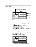
Display

PID set No. setting value

Program No.

Segment No.

Pattern

tendency

EV1 to EV3 and T1 to T5 all out

P


I


D

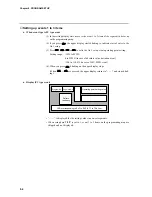
• When setup data 

C


1


1

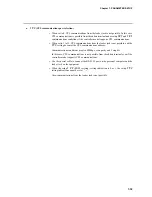
 is set to 1 and PID set auto-switching ON is selected, the PID set

No. items on the programming map are skipped and not displayed.

• On 5G output models, when setup data 

C


1


8

 is set to 1 and programmer functions are

selected, the PID set No. items on the programming map are skipped and not dis-
played.

• On 3D output models, when setup data 

C


4


5

 is set to 1 and 3-position-proportional

control is selected, the PID set No. items on the programming map are skipped and not
displayed.

• When setup data 

C


7


0

 is set to 1, the PID set No. items on the programming map are all

skipped and not displayed.

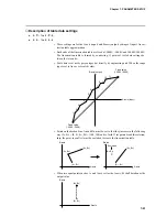
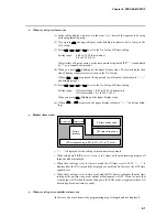
• When the PID set No. setting is set to 0, this means that the PID set No. of the previous

segment is continued. When the PID set No. setting is set to 0 in the No.1 segments,
this is the same as being set to 1.

Summary of Contents for DCP301

Page 1: ...EN1I 6197 Issue 7 02 04 DCP301 Digital Program Controller User s Manual ...

Page 2: ...f you encounter a problem with your unit please review all the configuration data to verify that your selections are consistent with your application i e Inputs Outputs Alarms Limits etc If the problem persists after checking the above parameters you can get technical assistance by calling the following In the U S A 1 800 423 9883 In Europe Your local branch office ...

Page 3: ...arns the user of the danger of electric shock White circles with a diagonal bar notify the user that specific actions are prohibited to prevent possible danger These icons graphically represent the actual prohibited action The example on the left notifies the user that disassembly is prohibited Black filled in circles instruct the user to carry out a specific obligatory action to prevent possible ...

Page 4: ...ecifications Insufficient tightening of terminal screws might cause electric shock or fire Do not use unused terminals on the DCP301 as relay terminals Doing so might cause electric shock fire or faulty operation We recommend attaching the terminal cover sold separately after wiring the DCP301 Failure to do so might cause electric shock fire or faulty opera tion Use the relays on the DCP301 within...

Page 5: ...ng battery fluid batteries Do not throw batteries into fires or charge short circuit disassemble or heat batteries Store batteries in low temperature dry locations Failure to observe the above cautions may cause batteries to emit heat or split or battery fluid to lead Store batteries out of the reach of small children Batteries are small and are easy to swallow If a child swallows a battery consul...

Page 6: ... are not in order immediately contact your dealer Name Model No Q ty Remarks See 1 5 How Model Nos Are Configured page 1 5 1 Mounting bracket 81405411 001 1 set 2 User s Manual EN1I 6197 1 This manual Unit indicator label SI units N 3132 1 Request The filter on the front of the controller is Covered with a protective film to protect the surface of the controller When you have finished mounting and...

Page 7: ... functions of the controller This chapter is required reading for designers of control systems using the DCP301 Chapter 6 OPERATION This chapter describes how to switch the basic display states of the DCP301 and select and run programs This chapter is required reading for designers of control systems using the DCP301 and users of the DCP301 Chapter 7 PARAMETER SETUP This chapter describes how to s...

Page 8: ...ions using two or more keys 2 7 Loader jack 2 7 2 3 Input Type and Range No 2 8 Inputs 2 8 Chapter 3 MOUNTING 3 1 External Dimensions 3 1 3 2 Panel Cutout Dimensions 3 2 3 3 Mounting 3 3 Mounting locations 3 3 Noise generating sources and countermeasures 3 4 Dust proof cover 3 4 Mounting method 3 5 Chapter 4 WIRING 4 1 Wiring Precautions 4 1 4 2 Compensating Lead 4 3 4 3 Terminal Connections 4 4 4...

Page 9: ...onnecting for Communications 4 16 RS 485 interface 4 16 4 14 Isolating Inputs and Outputs 4 19 Control outputs 0D 5G 6D 3D 5K 4 19 Control output 2G 4 19 Chapter 5 FUNCTIONS 5 1 Data 5 1 Data types 5 1 5 2 Program Patterns 5 2 Patterns 5 2 Events 1 to 3 5 3 Time events 1 to 5 5 6 PID set selection 5 8 G Soak guarantee soak 5 8 PV start 5 9 Cycle 5 9 Pattern link 5 10 5 3 Modes 5 11 Mode type 5 11 ...

Page 10: ...on of variable parameter settings 7 10 Event configuration data settings e v 7 18 Description of event configuration data 7 22 PID parameter settings p i d 7 23 Setup data settings S e t 7 27 Description of setup data settings 7 33 Table data settings T B L 7 40 Description of table data settings 7 41 Constant value operation data settings C N S T 7 42 Chapter 8 PROGRAM SETUP 8 1 Program Setup 8 1...

Page 11: ...ng in the basic display state 9 4 The controller does not change to MANUAL mode by pressing in the basic display state 9 4 The controller does not change to AUTO mode by pressing in the basic display state 9 4 Auto tuning AT is not started by pressing in the basic display state 9 4 Auto tuning AT is not canceled by pressing in the basic display state 9 5 Setting group other than p a R a is not dis...

Page 12: ...ssing in the basic display state 9 7 General reset is not applied by pressing in the basic display state 9 7 9 3 Motor Adjustment is Impossible 9 8 Normal wiring for direct motor rotation 9 9 Normal wiring for reverse motor rotation 9 9 Alarm display caused by wrong wiring and causes 9 9 9 4 Replacing the Battery 9 10 BAT LED blinking 9 10 Items to prepare 9 10 Replacement procedure 9 11 Chapter 1...

Page 13: ...te Notes indicate useful information that the user might benefit by knowing These icons represent keys on the DCP301 s console Combinations of icons like these indicate that must be pressed while holding down 1 2 3 The numbers with the parenthesis indicate steps in a sequence or indicate corresponding parts in an explanation Indicates the controller state after an operation PROG RUN HOLD RUN HOLD ...

Page 14: ...ble relay time proportional output position proportional output current output voltage time propor tional output and heat cool output On models other than heat cool control output you can also choose neural net based auto tuning and smart tuning for inhibiting overshoot in addition 2 degrees of freedom PID Enhanced compatibility with PLC 12 external switch inputs eight optional three event outputs...

Page 15: ...g Neuro Fuzzy Forward reverse action ON OFF control SP limit SP bias Output change limitter Upper lower limitter SP output Outputs Current Relay Voltage Position proportional Heat cool Event Outputs PV SP Deviation MV MFB Modes Alarm Time Event Outputs Time event Segment code Auxiliary Outputs PV SP Deviation MV MFB CPL communications I O Loader communications I O Program 19 patterns x 30 segments...

Page 16: ...operation of the controller Total of 19 program patterns SP Time Program No 19 Number of segments 8 SP Time Program No 3 Number of segments 15 Time Program No 2 Number of segments 19 SP 5 6 Time Program No 1 Number of segments 6 18 19 1 2 3 4 12 13 14 15 2 3 4 5 6 7 8 Parameters Variable parameters Event configuration data PID parameters Setup data Table data Constant value operation data ...

Page 17: ...iguration by CPL communications On DCP301 models supporting RS 485 communications optional controllers can be connected as slave stations on a communications network Personal computer master station DCP301 slave station RS 485 RS 232C RS 232C RS 485 converter ...

Page 18: ...ES Free power supply 90 to 264Vac 00 No auxiliary output 01 1 auxiliary output 02 2 auxiliary outputs 0 External switch inputs 4 time events not supported communica tions not supported 1 External switch inputs 12 5 time events supported communications not supported 2 External switch inputs 12 5 time events supported RS 485 commu nications supported 00 Additional treatment not supported T0 Tropical...

Page 19: ...ns console and electrical circuits Standard terminal base Add on terminal base Contains 7 segment display LEDs operation keys and loader connector Connectors for connecting power input output event outputs external switch inputs 4 and auxiliary outputs options Terminal for connecting external switch inputs 8 options time event outputs options and CPL communications options The add on terminal base...

Page 20: ...isplay Basic indicator LED lamps Upper display Lower display Low battery voltage LED BAT Control output state LED Profile display Program No display In the basic display state this display indicates the currently selected program No In the program setup state this display indicates the program No currently being set up During constant value operation this display goes out in the basic display stat...

Page 21: ...2 When relay or voltage are assigned to output 2 lights when output is ON and goes out when output is OFF In the case of 2G output models lights when the closed side relay is ON and goes out when the relay is OFF Lights when current output is assigned to output 2 and goes out when auxiliary output is assigned to output 2 OT3 Out Basic indicator LEDs PV Lights during PV display Otherwise this LED i...

Page 22: ...xecute running of program in READY mode To run the program in READY HOLD FAST modes To hold the program in RUN mode To reset the program in READY HOLD FAST END modes To advance the program in RUN HOLD FAST modes To run the program fast in RUN HOLD modes To execute manual operation in AUTO mode To execute automatic operation in MANUAL mode To start auto tuning when not executing auto tuning To canc...

Page 23: ... setting values while setting value is blinking To end changing assignment item setting values while setting value is blinking To start changing assignment item setting values To end assignment item setup To start program setup programming in basic display state To move between program items and segment Nos To start changing item setting values while setting value is blinking To end changing item ...

Page 24: ...el ling pencil or needle Doing so might damage the console To start program copy PROG in basic display state To change the copy destination program No To execute program copy ENT while setting value is blinking To end program copy DISP To check general reset FUNC CLR DISP in basic display state To execute general reset ENT To cancel general reset DISP Handling Precautions ...

Page 25: ... in the program operation mode in the basic display state to move to the program setup programming state Press PROG with FUNC held down in the program setup state to change the No of the program to be set up in ascending order FUNC Program No change keys Press with FUNC held down in the program setup state to change the No of the program to be set up in descending order FUNC CLR Program item delet...

Page 26: ...2372 DIN U 18 Z08 200 0 to 400 0 300 to 750 DIN L 19 Z07 200 0 to 800 0 300 to 1600 Golden iron 20 Z06 0 0 to 300 0K chromel Input Format Range No Code Temp Range C Temp Range F JIS 89 Pt100 32 F50 200 0 to 500 0 300 to 900 IEC Pt100Ω 33 F46 200 0 to 200 0 300 to 400 34 F32 100 0 to 150 0 150 0 to 300 0 35 F36 50 0 to 200 0 50 0 to 400 0 36 F38 60 0 to 40 0 76 0 to 104 0 37 F33 40 0 to 60 0 40 0 t...

Page 27: ...ut of code B18 is 20 C 68 F The lower limit readout C of codes K44 K46 T44 Z08 and Z07 is 199 9 C The lower limit readout C of codes F50 F46 P50 and P46 is 199 9 C The upper limit readout C of codes F01 and P01 The PV lower limit alarm does not occur with code F50 However note that the PV lower limit alarm occurs at a disconnection when input has been downscaled when input is disconnected during s...

Page 28: ...90 2 91 5 Back plate Add on terminal base Terminal screw 106x104 18 15 159 5 137 A B A B Unit mm Mounting bracket 81405411 001 Soft dust proof cover set sold separately 81446087 001 Hard dust proof cover set sold separately 81446083 001 Terminal cover set sold separately 81446084 001 96 96 ...

Page 29: ...rd dust prevention cover is used Panel cutout dimensions when mounting units horizontally and vertically recommended 3 2 Panel Cutout Dimensions Use a steel panel of at least 2mm in thickness for mounting the controller When mounting the controller take care to prevent the temperature at the lower surface of the controller s case from exceeding the operating temperature range 0 to 50 C particularl...

Page 30: ...sassemble the DCP301 Doing so might cause electric shock or faulty operation WARNING 3 3 Mounting CAUTION Mounting locations Avoid installing the DCP301 in the following locations Locations outside of the operating temperature range 0 to 50 C and operating humid ity range 10 to 90 RH Locations subject to sulfide gas or other flammable gases Locations subject to dust or oil smoke Locations subject ...

Page 31: ...sources and countermeasures Generally the following generate electrical noise 1 Relays and contacts 2 Solenoid coils solenoid valves 3 Power lines in particular 90Vac min 4 Induction loads 5 Inverters 6 Motor commutators 7 Phase angle control SCR 8 Wireless communications equipment 9 Welding equipment 10 High voltage ignition equipment If the influence of electrical noise cannot be eliminated we r...

Page 32: ... 1 first 1 Panel Panel Mounting bracket 2 To secure the controller tighten the screw on the mounting bracket supplied until there is no more play and then tighten a further full turn Take care not to overtighten the screw Doing so might deform the case Keep the mounting angle to within 10 from the horizontal at both the controller rear top and bottom Lift up from rear by 10 max Pull down from rear...

Page 33: ...lay terminals Failure to do so might cause electric shock fire or faulty operation We recommend attaching the terminal cover sold separately after wiring the DCP301 Failure to do so might cause electric shock fire or faulty op eration Use the relays on the DCP301 within the service life listed in the specifica tions Continued use of the relays after the recommended service life might cause fire or...

Page 34: ...tion When inputting the DCP301 s I O parallel connection in case of input to an A D converter or analog scanner read data may fluctuate To prevent this adopt one of the following measures 1 Use a low speed integrating type A D converter 2 Insert an isolator without a switching power supply between the DCP301 and A D converter 3 Average data on a personal computer when reading data 4 If possible se...

Page 35: ...rminal Use shielded compensating leads only For I O other than thermocouples use JCS 364 shielded instrument polyethylene insu lated vinyl sheath cable or equivalent product This is generally referred to twisted shielded cable for instruments The following cables are recommended Fujikura Ltd 2 core IPEV S 0 9mm2 x 1P 3 core ITEV S 0 9mm2 x 1T Hitachi Cable Co 2 core KPEV 0 9mm2 x 1P 3 core KTEV S ...

Page 36: ...lling the DCP301 in locations subject to vibration or impact be sure to use round crimped terminals to prevent the lead from coming loose from the terminal When wiring with crimped terminals take care to prevent contact with adjacent terminals The recommended tightening torque for the terminal screws is 0 78 to 0 98N m Handling Precautions ...

Page 37: ...d on terminal base The following diagram shows the recom mended draw out directions for the leads on the standard terminal base The lead draw out directions are the same when using the add on terminal base Standard terminal base Lead draw out direction Lead draw out direction 11 to 20 to left 1 to 10 to left 21 to 26 to left 26 to 34 to right ...

Page 38: ...ulating transformer in the power circuit and using a line filter Recommended line filter Model No 81446364 001 After providing anti noise measures do not bundle primary and secondary power leads together or pass them through the same piping or wiring duct Ground When it is difficult to ground shielded cable prepare a separate ground terminal earth bar Ground type 100Ω max Ground cable 2mm sq min s...

Page 39: ... Event outputs 2G output OD output 3D output 5G output 6D output 5K output Auxiliary output Relay Relay 4 to 20mA voltage 4 to 20mA voltage 4 to 20mA Output 1 Output 2 Auxiliary output 1 Auxiliary output 2 External switch input RSW Current input Input Resistance temperature detector Voltage input Thermocouple input Auxiliary output 4 to 20mA Recorder etc 44 45 46 47 48 43 41 42 55 56 53 54 51 52 4...

Page 40: ...g to the sensor being used Thermocouple input RTD input dc voltage input dc current input Applying voltage across dc current input terminals 31 and 33 may cause faulty operation Take care of polarities when wiring inputs Use only shielded cable for wiring inputs When using a thermocouple input prevent air blasts from coming into contact with the terminal Doing so might cause a reading error Handli...

Page 41: ...back resistance 100 to 2500Ω Load Load The life of internal relays is limited Avoid setting the PID constant in such a way that results in excessive repeated ON OFF switching When using a 100 200Vac motor pay attention to rush current and the contact rating If necessary provide an external auxiliary relay Separate the wiring for motor terminals 11 12 13 and feedback resistor terminals 14 15 16 Do ...

Page 42: ...a bleeder resistor to allow current flow of the minimum relay switching input 100mA min Heat cool output 5K Connect as follows 11 12 13 SSR 14 15 16 SSR Load Load Output 2 Output 1 Voltage output 2 to 22mAdc With current adjustment function setup C78 Current output 4 to 20 0 to 20mAdc Load resistance 600Ω max Voltage output 2 to 22mAdc With current adjustment function setup C79 Current output 4 to...

Page 43: ... output 2 4 to 20 0 to 20mAdc Resistive load 600Ω max Auxiliary output 2 output 3 4 to 20 0 to 20mAdc Resistive load 600Ω max 4 to 20mAdc and 0 to 20mAdc can be selected in setup data C 9 0 Use shielded cable only 2G 3D 5K auxiliary outputs 17 18 19 Receiver Auxiliary output 2 output 3 4 to 20 0 to 20mAdc Resistive load 600Ω max Auxiliary output 1 is not provided for 2G 3D and 5K outputs 4 to 20mA...

Page 44: ...5 EV1 1a EV2 1a EV3 1a1b Load Power supply Load Power supply Load Power supply Standard terminal base Contact rating resistive load 1A 30 250Vdc Contact rating resistive load 1A 30 250Vdc Contact rating resistive load 2A 30 250Vdc Minimum switching current 10mA When switching small currents connect a bleeder resistor to allow current flow of the minimum relay switching input 10mA min Handling Prec...

Page 45: ... sure to connect terminal 55 to the terminal of the external power supply Otherwise open collector output will not function Do not short circuit the terminal of the external power supply and terminals 49 to 53 on the DCP301 Doing so will cause faulty open collector output The DCP301 does not contain a short circuit prevention circuit When connecting to a semiconductor load such as a programmable c...

Page 46: ... open voltage 12Vdc Be sure to use no voltage contacts for external contacts Use no voltage contacts such as gold contacts whose small current can be switched ON OFF On some relay contacts the small current cannot be switched ON OFF Use no voltage contacts having a sufficient minimum switching ca pability with respect to the contact current and open voltage of the DCP301 When using a semiconductor...

Page 47: ...circuit for controller components for connecting external switch inputs 24 21 25 12Vdc 12Vdc 48 41 12Vdc 12Vdc Standard terminal base External switch input External switch input Internal circuit Internal circuit Add on terminal base ...

Page 48: ...base Multi drop connection of slave stations is possible Make sure that different addresses are set for each slave station Provide terminating resistor total of 4 in the case of a 5 wire system connec tion on both ends of the communications path Use terminating resistor of 150Ω 5 1 2W min In the case of a 3 wire system connection short circuit terminals 57 and 59 58 and 60 on the DCP301 Do not sho...

Page 49: ...esistor Terminating resistor Slave station DCP301 Shielded cable Shielded cable Shielded cable Master station Slave station DCP301 Slave station DCP301 Provide terminating resistor of 150Ω 5 1 2W min at both ends of the communications path Grounding of the shielded FG terminal should be carried out at only one end and not both ends Be sure to connect SG terminals each others Failure to do so might...

Page 50: ...RS 485 terminals terminals marked are wired internally 57 58 59 60 61 SDA SDB RDA RDB SG FG 57 58 59 60 61 SDA SDB RDA RDB RDA RDB SDA SDB SG FG SG FG 57 58 59 60 61 SDA SDB RDA RDB SG FG Terminating resistor Terminating resistor Slave station DCP301 Slave station DCP301 Slave station DCP301 Shielded cable Master station Shielded cable Shielded cable Be sure to connect SG terminals each others Fai...

Page 51: ...O Loader jack 12 external switch inputs Communications I O RS 485 Digital circuit 31 11 12 13 14 15 16 17 18 4 5 6 7 8 9 10 49 56 32 33 34 21 25 41 48 57 61 Input 1 full multiple input PV supported Output 1 control output 1a relay x 2 Motor feedback input Output 3 auxiliary output Event output 1 relay output 1a Event output 2 relay output 1a Event output 3 relay output 1a1b Time event outputs 1 to...

Page 52: ...1 to 8 Basic data that can be changed only in READY mode Linearization table data Data e g SP PID of constant value operation SP and time data Events 1 to 3 data Time events 1 to 5 time data PID set No data for use in control G Soak ON OFF data PV START ON OFF data Cycle count data Pattern link destination program No data Variable parameters Event configuration data PID parameters Setup data Table...

Page 53: ... of the current segment Accordingly segments are categorized as follows Rising ramp rising ramp rising tendency Previous segment SP setting value current segment SP setting value Falling ramp falling ramp falling tendency Previous segment SP setting value current segment SP setting value Soak soak Previous segment SP setting value current segment SP setting value In the case of the No 1 segment bo...

Page 54: ... and a down facing arrow indicates a change to OFF Event ON delay The event No to apply the delay to and the delay time can be set regardless of event type Delay functions to turn output ON when the event is continuously ON for the preset delay time after the event OFF ON condition is satisfied When event ON delay is combined with event standby event standby must first be canceled before event ON ...

Page 55: ...EV MV MV reverse H EV MFB MFB reverse H SP EV PV Deviation direct H H EV EV SP PV Absolute value deviation direct H EV SP SP direct H EV MV MV direct H EV MFB MFB direct H H EV EV SP PV Absolute value deviation reverse ON OFF ON OFF ON OFF ON OFF ON OFF ON OFF ON OFF ON OFF ON OFF ON OFF ON OFF ON OFF ...

Page 56: ...rwise the event is OFF Alarms Alarms are divided into PV range alarm groups alarm code Nos 01 to 16 and control ler alarm groups alarm code Nos 70 to 99 and low battery voltage When the event type is set to the sum of all alarms the alarm turns ON even if at least one of the alarms occurs When the event type is set to PV range alarm the alarm turns ON even if at least one of the alarms in the PV r...

Page 57: ... output is ON for the during from the ON time to the seg ment end point See segments 2 and 5 in the figure When both the ON time and OFF time are not set output is OFF See segment 3 in the figure Setting only the OFF time without an ON time is not possible See segment 3B in the figure Setting an ON time to be greater to or equal than the OFF time is not possible See segment 3C in the figure Only O...

Page 58: ...to T5 are selected as segment No events in the time event type setup all ON OFF operations are as shown in the following table When T1 to T4 are assigned in part to segment No events only the assigned time events operate as shown in the following table and the remaining events operate as regular time events 1 2 3 4 5 6 7 8 9 10 11 12 13 14 15 T1 ON OFF ON OFF ON OFF ON OFF ON OFF ON OFF ON OFF ON ...

Page 59: ...PID set selection G Soak guarantee soak G Soak ON OFF and G Soak width can be set for each seg ment The G Soak time can also be set by the variable param eter G S t item The G Soak function ensures a segment execution time with PV close to SP G Soak functions not only in soak segments but also in ramp segments At the segment start point PV and SP are compared and the absolute value of the resultin...

Page 60: ...r the segment at the pattern link destination Cycle The cycle function is for repeating operation from the No 1 segment of the program pattern to the final set segment for a preset number of cycles The number of cycles can be set up to 9999 When a number of cycles n is set the operation count becomes n 1 When executing cycle operation operation at the end point of the final segment is not carried ...

Page 61: ...endless loop If the SPs at the link source end point and the link desti nation start point do not match the SP changes in a stepped manner during link operation When cycle operation has been set the pattern link func tion works after cycle operation has ended After pattern link operation ends operation begins from the No 1 seg ment of the link destination pattern so operation is re started with th...

Page 62: ...Constant value operation Operation is carried out according to SP or events set in the constant value operation data Time events 1 to 5 turn OFF READY In this mode the DCP301 is ready for operation MV output is fixed and events to be operated according to event setting values turn OFF However events to be operated according to controller states are active Parameters for all of the setup data some ...

Page 63: ... is selected by the variable parameter F A S T setting MV outputs are active in PID control or ON OFF control and events and time events are active The controller does not enter the G Soak standby state even if G Soak Guarantee Soak is set The FAST mode is not available during constant value operation END In this mode operation of the program has ended MV outputs are active in PID control or ON OF...

Page 64: ...END at end of operation When shifting between the AUTO and MANUAL modes the modes in the square frames can be shifted between Selection of the READY or END modes at end of operation is set up in the setup data During constant value operation The solid lines in the following diagram shows mode transition operation When shifting between the AUTO and MANUAL modes the modes in the square frames can be...

Page 65: ...operation involves shifting to the FAST mode from the RUN or HOLD modes The FAST mode is not available in the constant value operation mode AUTO This operation involves shifting to the AUTO mode from the MANUAL mode MANUAL This operation involves shifting to the MANUAL mode from the AUTO mode When the DCP301 enters the MANUAL mode the basic display state changes as fol lows When controller functio...

Page 66: ...itch Com muni cations Com muni cations Key Switch Original mode READY RUN HOLD FAST END READY RUN Operation MANUAL AUTO to MANUAL mode to AUTO mode Original mode AUTO MANUAL AUTO MANUAL Com muni cations Key Switch Key Com muni cations Switch Constant value operation Program operation Program operation Constant value operation Operation is enabled Operation is enabled if in basic display state No 1...

Page 67: ...g manipulated variable MV is out put as an analog output ON OFF control heat cool PID control and 3 position proportional is also possible de pending on the type of output supported by the model of DCP301 In the MANUAL mode the MV can be incremented or decremented in the basic display state by the console keys PV MV DCP301 controller Controlled system Programmer When the DCP301 is used as a progra...

Page 68: ...wer limit value scaling Upper lower limit alarm Square root extraction Temperature unit range Linearization approximation Digital filter Bias PV1 DC current and voltage Setting Setup data C03 Setting Setup data C72 Setting Setup data C07 thermocouple and resistance temperature detector Setting Setup data C02 DC current and voltage Setting Setup data C04 to C06 Setting Setup data C08 Table data T A...

Page 69: ...MANUAL mode Current output 4 to 20mA 0 to 20mA Initialization of PID control operation PID control operation Output change limitter Output upper lower limit limitter Manipulated variable MV1 Output 1 AT execution MV in READY mode Preset manual value Manual MV MV at over range AT operation Setting Variable parameters 1 OUT rpi d Setting PID parameters p 1 d 8E PID parameters dP di dd PID parameters...

Page 70: ...et manual value Manual MV AT operation ON OFF control operation Setting PID parameters p 1 d RE PID parameters dP di dd PID parameters br Setting Variable parameters OTL Setting PID parameters OL OH Setting Variable parameter AT Setting Setup data C 12 C 13 Setting Setup data C 14 C 15 Setting Variable parameter DI FF Setting Setup data C 16 6D output Setting Setup data C78 Setting Variable parame...

Page 71: ... MV Preset manual value MFB automatic adjustment MV at over range AT operation Output 1 open side relay Output 1 closed side relay Setting Variable parameters 1 OUT rpi d Setting PID parameters p 1 d RE PID parameters dP di dd PID parameters br Setting Variable parameters OTL Setting Variable parameter AT Setting PID parameters OL OH Setting Setup data C 12 C 13 Setting Setup data C 14 C 15 Settin...

Page 72: ...MV operation Over range Manual MV 3 position control 3 position control operation Preset manual value MV in READY mode heat 3 position control MV in READY mode cool 3 position control operation 50 MV at over range Setting Variable parameters 1 OUT rpi d Setting PID parameters p 1 d RE Setting Variable parameters OTL Setting Setup data C 12 C 13 Setting Setup data C 14 C 15 Setting Variable paramet...

Page 73: ...etup data C 18 Setting Setup data C 19 C20 Setting Setup data C 19 C20 Auxiliary output 1 type Upper lower limit scaling Output 2 4mA 0mA Current output 4 to 20mA 0 to 20mA When READY mode is entered at auxiliary output type SP and deviation When auxiliary output type is NOP When auxiliary output type is set to MFB on non 2G output models When auxiliary output type is set to MV by program mer func...

Page 74: ...tinuation of AUTO MANUAL modes Continuation of manual value if in MANUAL mode Continuation of program No segment No Continuation of segment progress time Continuation of display No of basic display state in AUTO mode Parameter factory shipment setting Delete entire program Program operation mode READY mode AUTO mode Program No 1 1 segment No 1 Segment progress time 0 Cancellation of auto tuning sm...

Page 75: ...amp PV SP LED lit LED blinking PV SP Program segment No Display Basic indicator LED lamps Program No Segment No Pattern tendency Upper display Lower display Event LEDs Output states of events 1 to 3 time events 1 to 5 Supplementary explanation In the program operation mode READY indicates the currently selected program segment No Displays other than READY indicate the currently operating program s...

Page 76: ...ency Output states of events 1 to 3 time events 1 to 5 The digit to which SP values can be entered blinks in the MANUAL mode when pro grammer functions are selected Display 2 PV OUT PV Output value Program No Segment No Pattern tendency Output states of events 1 to 3 time events 1 to 5 The digit to which SP values can be entered blinks in the MANUAL mode when control ler functions are selected Dis...

Page 77: ...gment No Pattern tendency Output states of events 1 to 3 time events 1 to 5 Either of h min or min s is selected as the time unit in setup settings Select either remaining segment time or total operating time in setup settings as the details whose time is to be displayed Display 6 PV CYC PV Number of remaining cycles Program No Segment No Pattern tendency Output states of events 1 to 3 time events...

Page 78: ...details whose time is to be displayed Display in constant value operation mode DISP functions Output Model No Display 0D 5G 6D Display 1 Display 2 Display 1 repeated 2G Display 1 Display 2 Display 3 Display 1 repeated 3D 5K Display 1 Display 2 Display 4 Display 1 repeated Display 1 PV SP PV SP Output state of events 1 to 3 The digit to which SP values can be entered blinks in the MANUAL mode when ...

Page 79: ...put models output catalog No appended with 2G Display 4 OUT Heat side output Cool side output Output state of events 1 to 3 This display is exclusive to heat cool output models output catalog No appended with 3D or 5K Motor valve opening Output state of events 1 to 3 F B ...

Page 80: ...ion READY mode Each press of PROG increments the program No The display reverts to 1 after 19 Each press of decrements the program No The display reverts to 19 after 1 Both already set or non set program Nos can be selected The program No cannot be selected when selecting the program No by exter nal switch input The program No cannot be selected during constant value operation Pressing does not ch...

Page 81: ...everse action switching Status RSW8 Program No selection Weighting 1 Status RSW9 Program No selection Weighting 2 Status RSW10 Program No selection Weighting 4 Status RSW11 Program No selection Weighting 8 Status RSW12 Program No selection Weighting 10 Status With PV is valid only in the program operation mode and READY mode and the PV start RUN mode is entered regardless of the PV start setting i...

Page 82: ...N ON ON ON OFF OFF RSW11 8 OFF OFF OFF OFF OFF OFF OFF OFF ON ON RSW12 10 OFF OFF OFF OFF OFF OFF OFF OFF OFF OFF Program No Selection 0 1 2 3 4 5 6 7 8 9 External Weighting State Switch No RSW8 1 OFF OFF ON ON OFF OFF ON ON OFF OFF ON ON RSW9 2 OFF ON OFF ON ON OFF ON OFF OFF ON OFF ON RSW10 4 OFF OFF OFF OFF OFF ON OFF ON ON ON ON ON RSW11 8 OFF ON OFF ON OFF ON OFF ON OFF ON OFF ON RSW12 10 ON ...

Page 83: ... selected No up to the rising edge of the RUN signal is 0 4s min 2 The time from the rising edge of the RUN signal up to holding of the program No is 0 2s min 3 The time from holding of RUN signal OFF up to the rising edge of the RUN signal is 0 2s min 4 The time from the rising edge of the RUN signal up to holding of RUN signal ON is 0 2s min 5 The time from fixing of the selected No up to changi...

Page 84: ...ns On 5G output models when programmer functions are in operation with setup data C 18 setting 1 SP can be manually manipulated When SP is displayed in the basic display state only one digit in the SP value being entered blinks When the SP value is incremented or decremented by or the actual SP output also increments or decrements SP values differ from values being entered to setting items in that...

Page 85: ...uctuations in PV will not cause controller trouble Normally suitable values are written by setting variable parameter At setting to 1 or 3 However when executing auto tuning on a line that easily overshoots either set to 2 or also use smart tuning for carrying out overshoot inhibit control Setting to 3 ex ecutes AT by neural net so that the suitable value is calculated for wider range applica tion...

Page 86: ...roup 2 major items selection Setting group n major items selection Individual items Individual items Individual items DISP key FUNC PARA keys ENT key PARA key ENT key PARA key ENT key PARA key key key key PARA key key key PARA key key key PARA key key key P A R A E V P 1 D S E T T B L C N S T This parameter is not displayed when variable parameter L O C is 2 or 4 This parameter is not displayed wh...

Page 87: ... individual item is displayed the setting value blinks This state is referred to as the setting value entry state In this state pressing or can in crement or decrement the setting value that is blinking Also pressing or moves the position of the digit that is blinking If you press ENT when the setting value is at the desired value blinking stops the display returns to its normally lit state and th...

Page 88: ...ey key key key key key key key key DISP key key key key key Individual items minor items key stores setting values to memory key cancels storage of setting values to memory ENT PARA ENT stores setting values to memory PARA does not store setting values to memory C 0 1 C 0 2 C 0 3 C 0 1 C 0 2 C 0 3 C 1 1 C 1 2 C 1 3 C 8 1 C 8 2 C 8 3 C 9 1 C 9 2 C 9 3 C 9 1 C 9 2 C 9 3 C 9 9 C 0 0 C 0 9 C 1 0 C 1 9...

Page 89: ...ows you to call up individual items more easily in the following order FUNC PARA selection of setting group individual item matrix How to register assignment items To register an assignment item add the following base corresponding to the setting group to the item No and then set the resultant value to setup data C 5 5 to C 6 2 PARA assign ment items 1 to 8 Base Setting Group 1000 Constant value o...

Page 90: ...y adding item No 3 of F L to setup data radical 2500 2520 This is produced by adding item No 20 of F A S T to variable parameter radical 2500 C 5 5 C 5 6 C 5 7 C 5 8 For details on item Nos see 7 3 Parameter Setup List pages 7 7 to 7 42 When the PARA assignment item setting is set to a value that does not corre spond to an existing item that setting is ignored For example though factory setting 10...

Page 91: ...3 blinking PARA Display item by key assign ment item 8 blinking Display item by key assign ment item 1 normally lit PARA Display item by key assign ment item 2 normally lit PARA Display item by key assign ment item 3 normally lit PARA Display item by key assign ment item 8 normally lit PARA When invalid assignments are registered that item is skipped and the next registered item is displayed Items...

Page 92: ... AT is executed 2 Overshoot inhibited AT is executed 3 AT by neural net is executed Note On heat cool models is displayed and setting is not possible 0 Smart tuning is disabled 1 The brake value is fixed to inhibit overshoot 2 Overshoot is inhibited while automatically reviewing the brake value Note On heat cool models is displayed and setting is not possible 0 2 degrees of freedom PID is disabled...

Page 93: ...is setting is displayed on heat cool models Note On 5G output models is displayed and setting is not possible 5 to 120s relay output 1 to 60s voltage output Note On models whose output 1 is neither relay output nor voltage output is displayed and setting is not possible 5 to 120s relay output 1 to 60s voltage output Note On models whose output 2 is neither relay output nor voltage output is displa...

Page 94: ...is not possible 0 to fully open adjustment 500 Note On models other than 2G output models is displayed and setting is not possible On 2G output models when M C setting is 2 is displayed and setting is not possible fully closed adjustment 500 to 9999 Note On models other than 2G output models is displayed and setting is not possible On 2G output models when M C setting is 2 is displayed and setting...

Page 95: ...selection in the parameter setup state However note that items assigned to PARA can be called up by PARA in the basic dis play state When L O C is set to 3 the following keys are disabled Basic display state PROG program selection program selection RUN HOLD RUN HOLD PROG RUN HOLD RESET PROG DISP ADV FUNC FAST A M AUTO MANUAL AT AT start AT cancel FUNC CLR DISP general reset However note that MV wh...

Page 96: ...from READY AUTO to RUN AUTO When the power is turned ON in the RUN AUTO or HOLD FAST END AUTO mode At completion of auto tuning As the PV SP and PID parameters settings bear a relation to PID operation the first MV resulting from PID operation will not necessarily match the I O U t setting value R P I D PID operation initialization When SP changes suddenly by ADV advance operation rate action in P...

Page 97: ... to 2 when normal control is not being carried out due to inappropriate tuning of the PID constant for example Also hunting is more likely to occur when B R is set to a large value on quick starting lines Set the B R value to 0 then to 2 On heat cool models smart tuning does not function 2 P I D 2 degrees of freedom 0 2 degrees of freedom is disabled 1 2 degrees of freedom is enabled 2 degrees of ...

Page 98: ...mes which will considerably shorten its service life The factory setting is 5 Use this as a guideline and take the control results and motor service life into consideration when setting the dead zone MFB Dead zone Open side relay ON Closed side relay ON Control output Dead zone setting value Heat cool control dead zone On heat cool models this sets how the relationship between heat side output and...

Page 99: ...100 50 0 100 Cool side OH Heat side OL Heat side OH Cool side OL Note 1 On heat cool models this sets how the relationship between heat side output and cool side output should be processed with respect to the MV resulting from PID operation Note 2 Constants OL and OH function as follows Note 3 When MV 50 the heat side PID set is switched to When MV 50 the cool side PID set is switched to Note 4 PI...

Page 100: ...AST and END modes State Heat side Output Cool side Output MV 1 OFF 0 0 ON 100 0 0 0 2 OFF 0 0 OFF 0 0 50 0 3 ON 100 0 OFF 0 0 100 0 SP PV OFF ON OFF ON Output heat Output cool HY L DV L DV H HY H Even in 3 position control output is time proportional in the READY mode This is set in setup data C 1 6 MV heat in READY mode and C 1 7 MV cool in READY mode When connecting an actuator that may burn by ...

Page 101: ... relay to ON at all times when MV 100 0 to set the motor to a fully open or fully closed state to compensate this error However note that this error is not compensated when MV is limited to within 0 1 to 99 9 by the output limitter or when MV is 0 0 or less or 100 or more due to the control state The following are probable causes when estimated position control is likely to be car ried out Defecti...

Page 102: ... and the count value is written to M O P The time it took from fully closed to fully open is written to M t However note that if this time is 240 0s or more the time is taken as 240 0s When all adjustments are completed the controller returns to the basic display state 4 To cancel automatic adjustment press DISP When automatic adjustment begins you cannot press any keys other than DISP DISP is use...

Page 103: ...y 107 MANUAL 108 Auto tuning executing 109 Constant value operation 110 MFB estimated position control 111 Sum of all alarms 112 PV range alarm 113 Controller alarm 114 Low battery voltage 115 Console setup in progress 116 Loader setup in progress 117 ADV ON time 1s 118 to 199 NOP Note Setting can be changed only in READY mode 0 Standby OFF 1 Standby ON Note The controller stands by after power is...

Page 104: ...to tuning executing 109 Constant value operation 110 MFB estimated position control 111 Sum of all alarms 112 PV range alarm 113 Controller alarm 114 Low battery voltage 115 Console setup in progress 116 Loader setup in progress 117 ADV ON time 1s 118 to 199 NOP Note Setting can be changed only in READY mode 0 Standby OFF 1 Standby ON Note The controller stands by after power is restored and in th...

Page 105: ...Auto tuning executing 109 Constant value operation 110 MFB estimated position control 111 Sum of all alarms 112 PV range alarm 113 Controller alarm 114 Low battery voltage 115 Console setup in progress 116 Loader setup in progress 117 ADV ON time 1s 118 to 199 NOP Note Setting can be changed only in READY mode 0 Standby OFF 1 Standby ON Note The controller stands by after power is restored and in ...

Page 106: ...e time events 2 T1 and T2 are segment No events T3 to T5 are time events 3 T1 to T3 are segment No events T4 and T5 are time events 4 T1 to T4 are segment No events T5 is a time event 5 All T1 to T5 are segment No events Note On models not supporting time events is displayed and setting is not possible Settings can be changed only in the READY mode Time event type ...

Page 107: ...irect operating point 500 C hysteresis 10 C and standby ON are set When the mode changes from READY to the RUN mode at PV 550 C the controller enters the standby state so event output is turned OFF Standby functions only when the event type is set to PV type event and does not function when set to time event type or controller status type D L 1 event 1 ON delay time D L 2 event 2 ON delay time D L...

Page 108: ...tput models is displayed for items O L and O H and setting is not possible When I setting is not 0 is displayed for R E and setting is not possible When variable parameter S T setting is 0 smart tuning disabled is displayed for B R and setting is not possible When variable parameter 2 P 1 D setting is 0 2 degrees of freedom PID disabled the items for D P D 1 D D are not displayed On heat cool mode...

Page 109: ...control system setting the rate time to 1 3 to 1 4 of the integrating time is generally consid ered to be appropriate In a pressure or flow rate control system derivative action causes hunting Either set the D setting to 0 0 to disable derivative action or decrease the setting so that derivative action is almost negligible The latter solution is more frequently adopted The MV upper and lower limit...

Page 110: ...D set 5 Reset time PID set 5 Rate time PID set 5 MV lower limit PID set 5 MV upper limit PID set 5 Manual reset PID set 5 Brake PID set 5 Disturbance inhibit proportional band PID set 5 Disturbance inhibit reset time PID set 5 Disturbance inhibit rate time PID set 5 Proportional band PID set 6 Reset time PID set 6 Rate time PID set 6 MV lower limit PID set 6 MV upper limit PID set 6 Manual reset P...

Page 111: ...D set 7 Reset time PID set 7 Rate time PID set 7 MV lower limit PID set 7 MV upper limit PID set 7 Manual reset PID set 7 Brake PID set 7 Disturbance inhibit proportional band PID set 7 Disturbance inhibit reset time PID set 7 Disturbance inhibit rate time PID set 7 Proportional band PID set 8 Reset time PID set 8 Rate time PID set 8 MV lower limit PID set 8 MV upper limit PID set 8 Manual reset P...

Page 112: ...99 to 9999U Note When the input 1 range type is non linear is displayed and setting is not possible When the input 1 range type is changed from non linear to linear the original non linear range values remain The relationship between the analog inputs and readout values can be inverted by inverting the upper and lower limit values 0 0 to 10 0 ratio to input range Note 0 0 disables square root extr...

Page 113: ...meters C P 1 1 to C P 1 7 0 OFF 1 ON 10 to 110 Note When C 1 2 setting is 0 is displayed and setting is not possible 0 Bump less 1 Preset Note When the programmer function is selected operation is bump less regardless of the setting of C 1 4 10 to 110 Note When C 1 4 setting is 0 is displayed and setting is not possible 10 to 110 Note This setting is invalid even if the programmer function is sele...

Page 114: ...When set to NOP or to MFB on models other than 2G output models output is fixed to 4mA When set to SP or deviation output in the READY mode is fixed to 4mA 1999 to 9999U 199 9 to 999 9 Note When the auxiliary output type is MV or MFB the unit is Otherwise the unit is U 0 PV1 1 SP1 2 Deviation1 3 MV1 4 to 7 NOP 8 MFB 9 to 11 NOP Note When auxiliary output 2 is not supported is displayed and setting...

Page 115: ...put ON OFF The controller state can be switched ON OFF by communi cations 1000 to 5000 Note To set the No add the No of the item to be assigned to PARA to the following values for the setting group containing that item 1000 Constant value operation data 1500 PID parameter 2500 Variable parameter 3500 Event configuration data 4000 Table data 4500 Setup data Assignments to which a nonexistent No hav...

Page 116: ...ber of C 6 q settings 0 Compensated internally 1 Compensated externally Note When the input 1 range type is other than a thermo couple is displayed and setting is not possible 0 Upscale 1 Downscale Note This setting is valid when the input 1 range type is thermocouple resistance temperature detector or linear mV series 0 Input ON again enabled within time proportional cycle 1 Input ON again disabl...

Page 117: ...bps even parity 1 stop bit 3 4800bps no parity 2 stop bits Note On models not supporting communications is displayed and setting is not possible Note is displayed and setting is not possible Note Normally set to 0 Note is displayed and setting is not possible Note is displayed and setting is not possible 0 Add on terminal 1 to 15 Loader jack communications address 0 Improved 1 Compatible with DCP2...

Page 118: ...a rameter The result of this operation is taken as SP C 4 7 auxiliary output 1 lower limit C 4 8 auxiliary output 1 upper limit C 5 0 auxiliary output 2 lower limit C 5 1 auxiliary output 2 upper limit This is the scaling setting for auxiliary output The values of the upper limit setting and lower limit setting can also be inverted In the following example the type is set to MV at auxiliary input ...

Page 119: ... the total operation time is set to h min the time display is 1 3 0 In the FAST mode the time display changes according to the FAST scale if this pa rameter is set to either 0 or 1 C 6 6 PV display This selects PV display in the basic display state You can select between numerical display or no display at all The setting of this parameter does not influence PV related input processing PID operatio...

Page 120: ... with respect to the internal impedance of the SSR side can be obtained The following shows equivalent circuits and related formulas Description of Symbols 1 Details IO Setting output current of controller setting range 2 to 22mA VO Maximum applied load voltage approx 14 7V VSSR Actual input voltage to SSR VSSR Input rated voltage range of SSR VSSR MIN to VSSR MAX VSSR MIN Minimum input rated volt...

Page 121: ...s 3 and 4 formulas must be satisfied 3 formula VSSR MIN IO x Z VD VO N 4 formula VSSR VSSR MAX VSSR IO x Z VD 4 Equivalent circuit when N number of SSRs are connected in parallel DCP301 SSR 1 IO VO VSSR Z VD SSR N VSSR Z VD IO N IO N Formulas 5 and 6 formulas must be satisfied 5 formula VSSR MIN IO N x Z VD VO 6 formula VSSR VSSR MAX VSSR IO N x Z VD ...

Page 122: ...en a current of 8 9mA flows to a PGM the maximum voltage at both of its input terminals becomes 3 7V 0 0089 x 260 x 1 05 1 3 3 7V Accordingly 13 2 3 7 3 56 which means that three PGMs can be connected in series The above calculation assumes operation in the worst conditions For example even if four PGMs are connected in series they should operate normally if a volt age of 3V or more is applied to ...

Page 123: ...across A and B The resistance error of the Zener barrier connected to leads A and B cannot be adjusted unless it is 20Ω or less This adjustment is not required when a Zener barrier and an input other than an RTD are not used Once the Zener barrier has been adjusted compensation is carried out on the Zener barrier When using on an RTD without a Zener barrier re adjust without the Zener barrier 32 3...

Page 124: ...der jack is not possible and the C 9 3 setting becomes the CPL communications address Communications conditions are also 4800bps even parity and 1 stop bit In this case CPL communications is not possible from the addon terminal even if the controller model supports CPL communications Use the special cable to connect the RS 232C port on the personal computer and the loader jack on the equipment Whe...

Page 125: ...becomes X An x Bn 1 Bn An 1 An Bn Input linearization table approximation A1 Input linearization table approximation A2 Input linearization table approximation A3 Input linearization table approximation A4 Input linearization table approximation A5 Input linearization table approximation A6 Input linearization table approximation A7 Input linearization table approximation A8 Input linearization ta...

Page 126: ...arization table are fixed at 2000U 2000U and 10000U 10000U The linearization table is formed by connecting 11 points of table data settings be tween the two ends Table data is set not by percentages but directly by engineering unit When the range type is set to linear set scaled values Points on the broken line An and Bn must be set so that they increase in the following way A1 B1 0 0 A2 B2 100 10...

Page 127: ...R 0 to 30 0 disables the brake function D P 0 1 to 999 9 D I 1 to 3600s D D 0 to 1200 0 disables derivative action Note On 0D and 6D output models when P setting is 0 0 ON OFF control is enabled is displayed for items I D O L O H R E D P D I and D D and setting is not possible When variable parameter M C setting is 2 estimated position control only on 2G output models is displayed for items OL and...

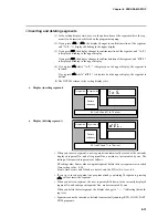
Page 128: ...lowing case When the program is protected variable parameter P R t C is set to 1 Display start items When the DCP301 enters the program setup state display starts from the program No and the segment No pattern item Selecting the program No to set up There are two ways of selecting the program No to set up Selecting the program No before entering program setup Selecting the program No after enterin...

Page 129: ... transition The following diagram shows the transition between modes during program setup The following page describes the various mode transition states 1 to 16 in the dia gram Program setup state Basic Display State Setting value display state No 2 setting entry state PROG FUNC DISP PROG FUNC FUNC keys keys 15 FUNC keys 12 keys 1 key 16 key 2 key 3 ENT key 4 ENT key DISP key 11 DISP key 11 DISP ...

Page 130: ...T is disabled for currently running programs 8 ENT clears the program from that segment onwards DISP does not clear the program and the setting display is returned to 9 No 2 setup setting value incremented decremented and blinking digit moved 10 Entry of No 2 setup is completed ENT stores the value being entered to memory When FUNC CLR are pressed at an event time event item the setting for that s...

Page 131: ... ON time 3 0 2 OFF time Event 3 1 Operating point ON time 0 0 0 0 0 0 0 0 0 2 OFF time 0 0 1 0 0 1 0 0 1 1 ON time 0 0 0 3 2 OFF time 1 0 0 1 ON time 1 0 0 2 OFF time 2 0 0 1 ON time 2 0 0 2 OFF time 3 0 0 1 ON time 2 OFF time 1 ON time 0 0 0 2 OFF time PID set No CH1 1 2 8 4 G Soak CH1 G Soak time out PV start 1 1 1 5 Cycle 0 0 0 Pattern link 0 0 0 Time event 1 Time event 2 Time event 3 Time even...

Page 132: ...ing Setting range SP1 lower to upper limit Set the SP1 limit in setup data C 0 Q or C 1 0 4 When you press ENT blinking on the upper display stops The lower display then starts blinking to indicate start of entry to the No 2 setup 5 Press or to set to the No 2 setup time setting Setting range 0 00 to 99 59 h min min s 0 0 to 599 9 0 1s Select either of h min or min s as the time unit in setup data...

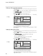
Page 133: ...etting Setting range 1999 to 9999U 0 to 9999U in case of absolute value deviation event 10 0 to 110 0 in case of MV MFB event 4 When you press ENT blinking on the upper display stops When FUNC CLR are pressed the upper display returns to and stops blink ing Display PV type event Operating point setting value Program No Segment No Pattern tendency LEDs corresponding to EV1 to EV3 lit T1 to T5 all o...

Page 134: ... 1 to 599 9 0 1s When you press ENT blinking on the upper display stops 6 When FUNC CLR are pressed the upper display returns to and stops blink ing Display time event ON time setting value OFF time setting value Program No Segment No Pattern tendency LEDs corresponding to EV1 to EV3 lit T1 to T5 all out is displayed for the setting values in non set segments When setup data C 6 8 is set to 1 even...

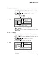
Page 135: ...e setting 0 1 to 599 9 0 1s 6 When you press ENT blinking on the upper display stops When FUNC CLR are pressed the upper display returns to and stops blinking Display ON time setting value OFF time setting value Program No Segment No Pattern tendency LEDs corresponding to EV1 to EV3 lit T1 to T5 all out is displayed for the setting values in non set segments On models that do not support time even...

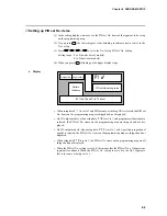
Page 136: ...t to 1 and PID set auto switching ON is selected the PID set No items on the programming map are skipped and not displayed On 5G output models when setup data C 1 8 is set to 1 and programmer functions are selected the PID set No items on the programming map are skipped and not dis played On 3D output models when setup data C 4 5 is set to 1 and 3 position proportional control is selected the PID ...

Page 137: ...kipped and not displayed Setting up G Soak time out items 1 In the setting display state move to the G Soak time out item of the segment to be set up on the programming map 2 If you press ENT the lower display starts blinking to indicate start of entry to the No 1 setup 3 Press or to set to the G Soak time out width setting Setting range 0 00 to 99 59 h min min s 0 0 to 599 9 0 1s Select either of...

Page 138: ...tting items pro vided for each program When setup data C 7 1 is set to 1 PV start items on the programming map are skipped and not displayed Setting up cycle items 1 In the setting display state move to the cycle items on the programming map The settings are common to all segments as the cycle items are setting items pro vided for each program 2 If you press ENT the lower display starts blinking t...

Page 139: ... move to the pattern item of the segment from which the program is to deleted on the programming map To delete all the segments of a particular program move to the No 1 segment 2 If you press ENT the upper display starts blinking to indicate start of entry to the No 1 setup So far the procedure is the same as that for setting the pattern item 3 If you press FUNC CLR the display changes to confirm ...

Page 140: ...nserting segment Display deleting segment When you insert a segment a new segment is automatically created at the currently displayed segment No and all segment Nos onward are incremented by one The setting of the inserted segment is as follows SP setting value Same value as original segment before the new segment was in serted Time setting value 0 10 Events time events and G Soak are not set and ...

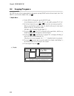
Page 141: ...e console when control ling the DCP301 by external switch inputs For details see 6 3 Program Selection page 6 7 3 If you press PROG C O P Y is displayed on the upper display and the copy destination program No is displayed on the lower display 4 If you press or currently non set program Nos are displayed blinking in order as the copy destination program No When there are no non set program Nos is ...

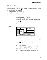
Page 142: ... at power ON If you press DISP general reset is not executed and the DCP301 returns to the basic display state Display Program No Segment No Pattern tendency Output state of events 1 to 3 time events 1 to 5 G R E S In the constant value operation mode all of the program No segment No and profiles displays are cleared If a RAM backup error occurs when the power is turned ON the display changes to c...

Page 143: ...n combination of different PCBs has been detected according to the catalog No of the controller The corresponding alarm code is displayed when this error is detected Self diagnostics at each sampling cycle Analog input error A probable cause of this error is a disconnected analog input This error is detected when the analog input is outside the 10 0 to 110 0 range The corresponding alarm code is d...

Page 144: ... the alarm codes are displayed from the smallest number upwards together with the regular display However note that when setup data C 6 7 has been set to 1 alarm codes are not dis played Alarm categories PV range alarm groups A L 0 1 to A L 1 2 Controller alarm groups A L 8 1 to A L Q Q and low battery voltage BAT LED on console blinks in case of low battery voltage Remedy Check input 1 Check line...

Page 145: ...the READY mode The controller is in the constant value opera tion mode Entry changeable display state by in MANUAL mode Key lock is enabled Set all external switch inputs RSW8 to 12 OFF Reset the controller Set constant value operation data M O D E setting to 0 Set variable parameter L O C setting to 0 to 2 The controller does not change to RUN mode by pressing RUN HOLD in the basic display state ...

Page 146: ...constant value operation data M O D E setting to 0 Set variable parameter L O C setting to 0 to 2 The controller does not change to MANUAL mode by pressing A M in the basic display state ON OFF control is being carried out by 0D and 6D outputs 3 position proportional control is selected by 3D output Key lock is enabled Cause Remedy Set PID set P setting in use to other than 0 0 and switch to PID c...

Page 147: ...he lower display Cause Remedy This cannot be displayed nor set This item sometimes can be displayed or set by changing the setting of related items This is a display only item The controller does not change to setup group selection state and setting entry state continues by pressing PARA in parameter setting entry state The controller displays items by PARA assign ment Cause Remedy Press DISP to r...

Page 148: ...support time events Programming items are set to display OFF Cause Remedy Change event configuration data T T setting and assign to time event Select a mode that supports time events option Set setup data C 6 q setting to 0 PID set auto switching is set to ON The controller is set to programmer function by 5G output 3 position control is selected by 3D output Programming items are set to display O...

Page 149: ...Cause Remedy Reset the controller The mode is not the READY mode The program of the currently selected pro gram No is not set up The controller is in the constant value opera tion mode The program is protected Key lock is enabled Cause Remedy Reset the controller Select a program No whose program is already set Set constant value operation data M O D E setting to 0 Set variable parameter P R T C s...

Page 150: ...ring the motor to the DCP301 for direct motor operation CW Clock Wise CCW Counter Clock Wise The DCP301 is also provided with a function A L 1 0 to A L 1 2 for detecting MFB disconnection or short circuit if the motor has been wired to the controller in the wrong way By this function the DCP301 judges reverse direction wiring in the same way as direct direction wiring and does not generate an alar...

Page 151: ... direct rotation Normal wiring for reverse motor rotation Upper Display Lit LEDs Lower Display Motor Action Remarks C A C L OT2 CW C A O P OT1 CCW Readout decreases from 9000 to 500 and stabilizes Readout increases from 500 to 9500 and stabilizes If the motor rotates CW when 1 2 and G Y are reversed and OT2 lights motor terminals 1 and 2 are wired for reverse rotation Alarm display caused by wrong...

Page 152: ...fore handling components inside the controller touch a grounded metal part to remove any static electricity from the body Static electricity may cause dam age to controller components Batteries left in storage for a long time discharge electricity reducing their ser vice life Purchase new batteries as required The parameter setups and program setups on the DCP301 are stored to battery backed up me...

Page 153: ...lacing the battery Insert the new battery on the RAM board within 24h of turning the controller OFF When the BAT LED starts blinking follow the procedure below to replace the battery 1 Leave the controller turned ON for at least 1h 2 Turn the power OFF 3 Remove the key cover from the console and fully loosen the lock screw under ENT with a Phillips screwdriver The body comes out towards you Batter...

Page 154: ... placing the RAM board on the desk make sure that the solder surface of the board is face down If the component mounting surface is placed face down the components may become damaged Connector Connector RAM board approx 3cm x 8cm 9 Remove the battery connector from the RAM board 10 Connect the connector of the new battery to the RAM board making sure that it is inserted the correct direction 11 Mo...

Page 155: ...ller under standard operating conditions operat ing temperature 23 2 C with the controller ON About 10 years when using the controller under standard operating conditions operat ing temperature 23 2 C with the controller OFF Using the controller in a higher operating temperature will shorten its service life Setups are held in memory even if the BAT LED is blinking The controller operates in one o...

Page 156: ...mocouple dc voltage input 1 3µA max at peak value under standard conditions At 1V min range 3µA max dc current input 50Ω 10 under operating conditions RTD input 1 04mA 0 02mA current flow from terminal A under operating conditions Changes in readout value at wiring resistance of 250Ω at both ends are as follows by input conversion 0 to 10mV 10 to 10mV Within 35µV 0 to 100mV Within 60µV Other Withi...

Page 157: ... and voltage ranges 12 both line ends fixed 11 points variable 1000 to 1000U variable 0 0 to 120 0s variable filter OFF at 0 0 12 Dry contacts relay contact and open collector current sink to ground 10 4 to 12 6V under operating conditions across common terminal terminal 25 and each input terminal 5 0 to 6 6mA across each terminal under operating conditions ON 700Ω max under operating conditions O...

Page 158: ...ets for program operation 1 set for constant value operation Segment designation automatic zone selection can be switched by program operation 0 0 to 10 0 0 01s no limit by 0 0 Automatic setting of PID value by limit cycle system Neuro Fuzzy 2 degrees of freedom PID and Smart systems executable by 0D 2G 5G and 6D outputs 0 to 1000U settable by 0D and 6D outputs 0 5 to 25 0 settable by 2G output 10...

Page 159: ...ated position can be selected Output current 4 to 20 0 to 20mAdc Allowable load resistance 600Ω max under operating conditions Output accuracy 0 1 FS max under standard condi tions 0 5 FS at output 5 or less of 0 to 20mA output Output resolution 1 10000 Inrush current 25mA max for 50ms max at 250Ω load Max output current 22 0mAdc Min output current 0 0mAdc Output updating cycle 0 1s Open terminal ...

Page 160: ...at rating Min switching voltage current 10V 10mA External supply voltage 10 to 29Vdc Max load current 70mA load OFF leakage current 0 1mA ON residual voltage 1 6V max PV type events PV deviation absolute value deviation SP MV MFB Controller status events RUN HOLD FAST END READY RUN HOLD FAST END G Soak standby MANUAL auto tuning executing constant value operation MFB estimated position control sum...

Page 161: ...er ON Approx 10 years under standard conditions 90 to 264Vac 50 60Hz 30VA max 15A max 10ms under operating conditions When starting up a number of DCP31s simultaneously ensure ample power is supplied or stagger startup times Otherwise the controllers may not start normally due to inrush current induced voltage drop Voltage must stabilize within 2s after power ON Reset time 15s max time until norma...

Page 162: ...rec tions 0 to 490m s2 3 times vertically Drop height 60cm 1 angle 3 edges and 6 planes free fall IEC127 Delayed operation type T 250V 1A M3 5 self tapping screw 0 78 to 0 98N m Mask Multilon Case Polycarbonate Mask Dark gray Munsell 5Y3 5 1 Case Light gray Munsell 2 5Y7 5 1 Specially designed mounting bracket Approx 900g Item Model No Q ty Standard accessories Unit indicating label N 3132 1 Mount...

Page 163: ...Chapter 10 SPECIFICATIONS 10 8 106x104 18 15 159 5 137 A B A B Unit mm 96 96 B B 37 78 4 110 5 A A 90 2 91 5 10 2 External Dimensions ...

Page 164: ...6 6 106 Packing Terminal cover set sold separately gray non flammable heat resistant PVC Model No 81446084 001 5 5 13 7 51 6 69 6 79 90 90 17 45 R1 8 5 3 6 hole Can be attached to either of standard or add on terminal base Soft dust proof cover set sold separately transparent silicon rubber Model No 81446087 001 98 86 27 5 16 12 5 15 5 2 7 3 2 1 5 95 98 Unit mm ...

Page 165: ...ment needed for calibration has stabi lized Factory calibration has been made at a stable temperature of 23 0 C 2 C Calibrate the DCP301 and DCP302 in this range and where there are no significant fluctuations in air temperature If calibration equipment of a lower grade than specified below is used calibration results may be unsatisfactory Equipment needed 1 Standard input source with 0 02 accurac...

Page 166: ...t DO Control Output Ch2 Test DO Control Output Ch3 Test DO Test 1 to 3 Event DO Test 4 to 8 Time Event Gain No 0 to 12 Gain No 16 to 20 Output Ch1 Output Ch2 Output Ch3 0 PV Input Calibration 1 CJ Sensor Calibration 2 Current Output Calibration 4 Option2 1 2 Basic Model DCP301 Model Output and Option Model Number Output 5G 6D Output 0D Output 2G 3D Output 5K Option1 00 Option1 01 Option1 02 Option...

Page 167: ...Gain No PV input 0 PV input 100 Item change code CJ input 0 CJ count CJ temperature Item change code OUT ch1 4mA output OUT ch1 20mA output OUT ch2 4mA output OUT ch2 20mA output OUT ch3 4mA output OUT ch3 20mA output 0 1 0 1 2 3 4 5 0 1 2 3 2 0 1 2 3 4 0 1 2 3 4 5 6 Item Sub Item Notes 1 Items No is shown on the PROG display 2 Sub item No is shown on the SEG display 3 Item 0 Function check item 4...

Page 168: ...F of display ON OFF of display DI test DI ON OFF Control output test Relay Voltage pulse Do output test PV input calibration item 1 0 1 1 A d J S Gain No selection 0 0 0 0 0 A d J S Zero input count After stabilized press Span input count After stabilized press Input of Control output ON OFF Input of DO ON OFF 0 0 0 0 A d J S PROG SEG 0 0 0 0 PROG SEG 0 0 0 3 PROG SEG 0 0 0 4 PROG SEG 0 0 0 5 PROG...

Page 169: ...d J S PROG SEG 0 0 0 2 PROG SEG 0 2 0 2 PROG SEG 0 2 0 3 PROG SEG 0 4 0 0 PROG SEG 0 4 0 1 PROG SEG 0 4 0 2 PROG 0 4 SEG 0 6 Current output count value Current count value stored Current output count value Current count value stored Current output count value Current count value stored ENTER SETUP SETUP SETUP SETUP SETUP SETUP SETUP ENTER Current input count No Current count No stored Current coun...

Page 170: ...t repeat the above procedure after pushing DISP key to refresh the display 4 To select individual calibration items press or keys to select the item by scrolling then PARA key and ENT key The order of calibration items is described in Table 11 2 Figure 11 3 0 0 0 0 A d J S 00 00 AT ENT FUNC A M PARA CLR LOADER PROG RUN HOLD DISP RUN HLD MAN PRG PROFILE PROG SEG PV SP OUT TM CYC CH1 CH2 BAT AT OT1 ...

Page 171: ...in the upper display shown in Table 11 3 Table 11 3 Upper Display HANDLING PRECAUTIONS 1 When you press DISP key calibration mode will be exited 2 When you press PARA key the next calibration menu will be entered Display test 0 0 4 0 0 0 2 0 0 0 0 4 0 0 0 8 0 8 0 0 Key Data 4 0 0 0 0 0 0 1 0 1 0 0 0 2 0 0 0 0 1 0 1 0 0 0 Key Data PROG CLR RUN HOLD A M FUNC AT ENT 11 7 Chapter 11 CALIBRATION ...

Page 172: ...each remote switch the upper display will show the data described in Table 11 4 Table 11 4 DI 0 0 0 0 0 0 0 1 0 0 0 2 0 0 0 4 0 0 0 8 0 0 1 0 0 0 2 0 0 0 4 0 0 0 8 0 0 1 0 0 0 2 0 0 0 4 0 0 0 8 0 0 ON DI Terminal Number Upper Display Notes 1 ON means to short the terminals by a jumper 2 means to open the terminals Example 21 25 22 25 ON 23 25 ON 24 25 ON 41 25 ON 42 25 ON 43 25 ON 44 25 ON 45 25 O...

Page 173: ...ation Table 11 5 Digital output test for event 00 05 Press PARA key until the PROG SEG display shows 00 05 Table 11 6 DO 0 0 0 0 0 0 0 1 0 0 0 2 0 0 0 4 0 0 0 8 0 0 1 0 0 0 2 0 0 0 4 0 0 0 8 0 ON DO Terminal Number Upper Display Notes 1 in the table means OFF 2 Since the DO hardware is of open collector specification the ON OFF check must be performed in meeting with the specification 4 5 6 7 ON 8...

Page 174: ...nal equal to the 100 range value See Table 11 9 and table 11 10 c Press ENT key after display stabilizes Table 11 9 Table 11 10 Gain No 16 17 18 19 20 PV Input 0 PV Input 100 8 000mV 20 000mV 1 000V 10 000Ω 0 000Ω 20 000mV 70 500mV 11 000V 380 000Ω 110 000Ω Connecting Position Between 28 and 29 Between 28 and 29 Between 27 and 26 Between 30 and 29 Between 30 and 29 Gain No 0 1 2 3 4 5 6 7 8 9 10 1...

Page 175: ...67 68 69 70 71 72 73 Group Range Table of CH1 RTD RTD Type Code Range No JIS 89 Pt100 IEC Pt100Ω JIS 89 JPt100 F50 F46 F32 F36 F38 F33 F05 F03 F01 P50 P46 P32 P36 P38 P33 P05 P03 P01 32 33 34 35 36 37 38 39 40 48 49 50 51 52 53 54 55 56 Range No 0 1 2 3 4 5 6 7 8 9 10 11 12 13 14 15 16 17 18 19 20 Gain No 9 9 9 9 10 10 9 9 10 9 9 9 9 10 10 9 9 10 Gain No 8 8 4 3 0 5 5 6 6 7 Group T C Range Table o...

Page 176: ...ess ENT key Connect the digital ammeter across terminals See Figure 11 9 OUT CH1 output calibration 1 Press PARA key until the PROG SEG display shows 04 01 Scroll or keys until meter indicates 4 00mA then press ENT key 2 Press PARA key until the PROG SEG display shows 04 02 Scroll or keys until meter indicates 20 00mA then press ENT key OUT CH2 output calibration 1 Press PARA key until the PROG SE...

Page 177: ...enerators 4 20mA 33 31 PV CH1 Copper leads Copper leads PV CH1 PV CH2 34 33 32 Decade resistance box 30 29 28 Decade resistance box Copper leads PV CH1 PV CH2 34 33 32 Decade resistance box 30 29 28 Decade resistance box Copper leads PV CH1 PV CH2 34 33 32 Decade resistance box 30 29 28 Decade resistance box 34 33 PV CH1 Millivolt sources 28 29 PV CH2 Copper leads Millivolt sources 11 13 Chapter 1...

Page 178: ...Figure 11 11 Current Outputs 14 15 17 18 11 12 CH3 OUT CH1 CH2 OUT OUT Digital ammeter Copper leads 11 14 Chapter 11 CALIBRATION ...

Page 179: ...H1 G Soak time out PV start Cycle Pattern link 1 2 1 2 1 2 1 2 1 2 1 2 1 2 1 2 1 2 SP1 Time ON OFF ON OFF ON OFF ON OFF ON OFF ON OFF ON OFF ON OFF 1 2 3 4 5 6 7 8 9 10 11 12 13 14 15 16 17 18 19 20 DCP301 Programming Map Draft Form Program No Date Unit name Product name Setting value Unit Programming Map Time Unit hours minutes minutes seconds ...

Page 180: ...oltages 90 to 264Vac Frequency 50 60Hz Power or current ratings 30VA maximum EQUIPMENT CONDITIONS Do not operate the instrument in the presence of flammable liquids or vapors Operation of any electrical instrument in such an environment constitutes a safety hazard Temperature 0 to 50 Humidity 10 to 90 RH Vibration Frequency 10 to 60Hz Acceleration 1 96m s2 maximum Installation category Category II...

Page 181: ...2 1 2 2 2 4 Constant value operation 5 11 5 13 Constant value operation data setting 7 42 Constant value operation display 6 5 6 6 Control outputs outputs 1 2 connection 4 9 Current output 5G Heat cool output 3D Heat cool output 5K Position proportional output 2G Relay output 0D Voltage output 6D Control output state LED 2 2 2 3 Controller function 5 16 Controller status events 5 5 CPL communicati...

Page 182: ... Mounting locations 3 3 Mounting method 3 5 MV change limit 7 11 N Noise 3 4 O ON OFF control differential 7 13 Optional parts 10 7 Output processing functions 5 18 Auxiliary output Control output SP output P Panel cutout dimensions 3 2 Parameters set up 7 1 Pattern link 5 10 8 12 Patterns 5 2 8 5 PID operation initial MV 7 11 PID operation initialization 7 11 PID set automatic switching 5 8 PID s...

Page 183: ...figuration 1 4 T Table data settings 7 40 Terminal cover set 3 1 10 7 10 9 Terminals connection 4 4 Thermocouple inputs 2 8 4 8 Time display 6 4 7 34 Time event output open collector connection 4 13 Time event outputs 1 2 Time events 1 to 5 selection 5 6 Time events 5 5 5 6 Trouble during key entry 9 3 U Upper display 2 2 2 3 V Variable parameter settings 7 7 Varister 3 4 Voltage output 1 adjustme...

Page 184: ...me out items added 10 6 SAFETY Applicable standards added EN61326 REQUIREMENTS Programming G Soak time out added Map Draft Form 03 08 6th Edition 4 3 Fujikura Cable Co Fujikura Ltd 4 17 4 18 Handling Precautions added to connect SG terminals each others 8 5 8 7 8 8 Setting range 0 0 to 599 9 0 1s added 8 7 8 8 ON time setting 0 1 to 599 9 0 1s added 8 10 Setting range changed 0 to 1000U to 0 00 to...

Page 185: ...L BERKS RG12 1EB UNITED KINGDOM Tel 44 344 424 555 VENEZUELA HONEYWELL CA APARTADO 61314 1060 CARACAS VENEZUELA Tel 58 2 239 7533 NORWAY HONEYWELL A S Askerveien 61 PO Box 263 N 1371 ASKER NORWAY Tel 47 66 90 20 30 PORTUGAL HONEYWELL PORTUGAL LDA Edificio Suecia II Av do Forte nr 3 Piso 3 CARNAXIDE 2795 LINDA A VELHA PORTUGAL Tel 351 4172 602 REP OF SINGAPORE HONEYWELL PTE LTD BLOCK 750E CHAI CHEE...

Page 186: ...6 59 JAPAN HONEYWELL KK 14 6 Shibaura 1 chome Minato ku Tokyo 150 0023 Japan Tel 81 3 5440 1395 ASIA PACIFIC HONEYWELL ASIA PACIFIC Inc Room 3213 3225 Sun Kung Kai Centre No 30 Harbour Road WANCHAI HONG KONG Tel 852 829 82 98 AUSTRIA HONEYWELL AUSTRIA G m b H Handelskai 388 A1020 VIENNA AUSTRIA Tel 43 1 213 300 BRAZIL HONEYWELL DO BRAZIL AND CIA Rua Jose Alves Da Chunha Lima 172 BUTANTA 05360 SAO ...

Page 187: ...No CP UM 5093E ...

Reviews: