Chapter 5. FUNCTIONS
5-3
■
Events 1 to 3
Events 1 to 3 are event configuration data. These are used after setting the event type,
event standby, hysteresis and ON delay time.
A total of three event types are available: PV type events, controller status events, and
time events.
●
PV type events
• Basic specifications
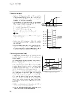
The following page shows event type PV, deviation, absolute value deviation, SP, MV
and MFB. In the figures, the thick lines show ON-OFF changes in state. The upper line
expresses the ON state, and the lower line the OFF state.
EV and H stand for event setting value and hysteresis, respectively. Output in the
READY state is OFF.
• Event standby
Events function as follows when event standby has been set to ON.
- If the controller is in the
state in the figure when changing from the READY to
the RUN mode and after restoring the power, operation is the same as when event
standby is set to OFF. The up-facing arrow in the figure indicates a change to ON,
and a down-facing arrow indicates a change to OFF.
- If the controller is outside the
state in the figure when changing from the READY
to the RUN mode and after restoring the power, the state is OFF. After entering the
state, the up-facing arrow in the figure indicates a change to ON, and a down-
facing arrow indicates a change to OFF.
• Event ON delay
The event No. to apply the delay to and the delay time can be set regardless of event
type. “Delay” functions to turn output ON when the event is continuously ON for the
preset delay time after the event OFF
→
ON condition is satisfied.
When event ON delay is combined with event standby, event standby must first be
canceled before event ON delay functions.
• Segment progression
- Output is OFF until the program progresses to the segment containing the event
setting.
- When the program progresses to the segment containing the event setting, event ON/
OFF operation is carried out according to the event setting value.
- The previous setting is valid until the program progresses to a segment containing a
new event setting.
For this reason, set as follows to disable the event set in the previous segment from a
certain segment onwards:
Direct action events:
Upper limit value of event setting
Reverse action events: Lower limit value of event setting
Note, however, that some types of event turn ON even if events are set as shown
above.
- When the program has progressed to the No.1 segment by the cycle or pattern link
functions, the previous setting is disabled. Output is OFF unless the No.1 segment
contains an event setting.
• Other
On 5G output models, when setup data
C
1
8
is set to 1, and SP output (programmer
functions) is selected, the MV direct/reverse event does not function.


