Chapter 5. FUNCTIONS
5-7
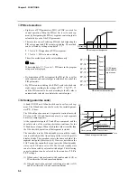
Segment
8
ON time
OFF time
Output ON
Output OFF
G.Soak standby
Segment
9
ON time
OFF time
Output ON
Output OFF
ON=segment time
Segment
10
Segment time
ON time
OFF time
Output ON
Output OFF
END mode
ON=segment time
Segment 8 time start
When 0N=0, output turns
ON when there is input to
segment 8.
• If the ON time is set to 0 in the case of G.Soak
standby, output becomes ON from the G.Soak
standby state, and the ON time is started at
completion of the G.Soak standby time.
The output time = G.Soak time + OFF time
(See segment 8 in the figure.)
• ON and OFF time settings the same time as
the segment end point are valid in the case of
the final segment END mode.
(See segment 10 in the figure.)
●
Segment No. events
The current segment No. is output as binary code.
When all of T1 to T5 are selected as segment No. events in the time event type setup, all
ON-OFF operations are as shown in the following table.
When T1 to T4 are assigned in part to segment No. events, only the assigned time events
operate as shown in the following table, and the remaining events operate as regular time
events.
1
2
3
4
5
6
7
8
9
10
11
12
13
14
15
T1
ON OFF ON OFF ON OFF ON OFF ON OFF ON OFF ON OFF ON
T2
OFF ON
ON OFF OFF ON
ON OFF OFF ON
ON OFF OFF ON
ON
T3
OFF OFF OFF ON
ON
ON
ON OFF OFF OFF OFF ON
ON
ON
ON
T4
OFF OFF OFF OFF OFF OFF OFF ON
ON
ON
ON
ON
ON
ON
ON
T5
OFF OFF OFF OFF OFF OFF OFF OFF OFF OFF OFF OFF OFF OFF OFF
16
17
18
19
20
21
22
23
24
25
26
27
28
29
30
T1
OFF ON OFF ON OFF ON OFF ON OFF ON OFF ON OFF ON OFF
T2
OFF OFF ON
ON OFF OFF ON
ON OFF OFF ON
ON OFF OFF ON
T3
OFF OFF OFF OFF ON
ON
ON
ON OFF OFF OFF OFF ON
ON
ON
T4
OFF OFF OFF OFF OFF OFF OFF OFF ON
ON
ON
ON
ON
ON
ON
T5
ON
ON
ON
ON
ON
ON
ON
ON
ON
ON
ON
ON
ON
ON
ON
Event No.
Segment
No.
Event No.
Segment
No.


