84
Emergency Command Center Manual —
P/N LS10001-000FL-E:G 5/3/2016
Section 4: Operating Instructions
4.1 Main Control Panel Keypad Labels
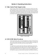
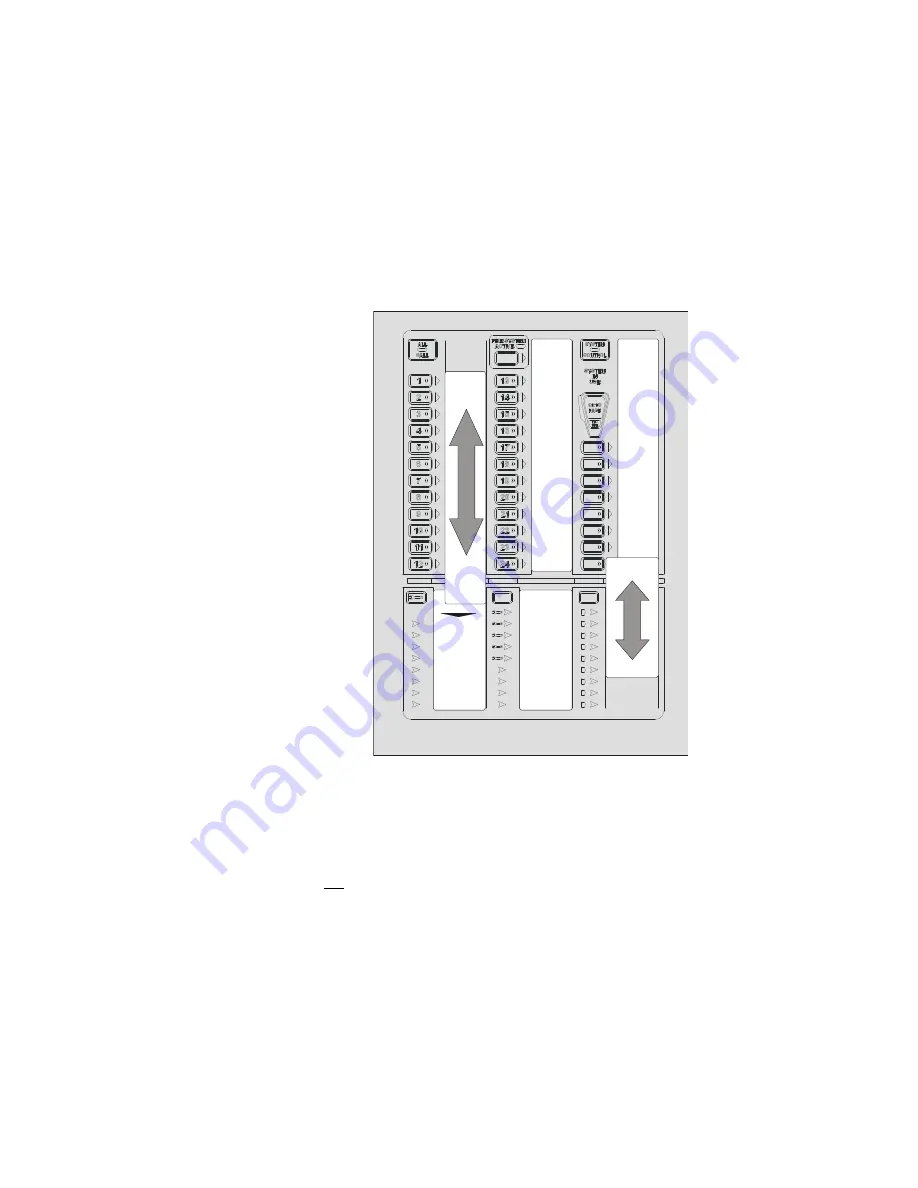
The ECC-50/100 is shipped with slide-in labels installed in the keypad as illustrated in the follow-
ing figure. Blank labels are provided to allow the user to customize the zone and message descrip-
tion. Remove the center piece to access the label slots. Using a small, flat screwdriver, press and
release the small plastic latch located on the left side of the center piece. The top row of labels can
be easily removed by sliding them down through the slots in the middle of the keypad and installed
by sliding them up. The bottom row of labels can be removed by sliding them up through the slots
in the middle of they keypad and installed by sliding them down into position.
4.2 ECC-50/100 Switch Functions
The ECC-50/100 display consists of 38 tactile push-button keys. Pressing one or more of the keys
while the panel is not in alarm will select the corresponding circuit for paging or to generate a man-
ually activated evacuation or drill signal. If the panel is in alarm, pressing a key corresponding to an
activated speaker circuit will turn off the circuit and turn on the Trouble LED.
All Call
Pressing this button activates all speaker circuits (that were not manually deactivated) for broad-
cast. ALL CALL paging from the main console's microphone will override paging/manual activa-
tion operations initiated from the other consoles (ECC-LOC, ECC-RPU, ECC-RM) or from a
FACP (if programmed for priority to do so). If all consoles in the system are programmed for equal
priority then the ALL CALL will only occur when the system is not already in use (“System in
Use” LED is not on, remote console active LED is not on). Refer to the SYSTEM CONTROL but-
Figure 4.1 Keypad Labels
e
c
c
k
y
lb
l.
w
m
f
Remove
Install
Install
Remove
TROUBLE SILENCE
AC POWER
GROUND FAULT
CHARGER FAULT
BATTERY FAULT
DATA BUS FAULT
NAC FAULT
NAC ACTIVE
SYSTEM TROUBLE
AUDIO RISER FAULT
DIST. AMP 1
DIST. AMP 2
DIST. AMP 3
DIST. AMP 4
DIST. AMP 5
DIST. AMP 6
DIST. AMP 7
DIST. AMP 8
REMOTE AMPS
SPEAKER
ZONE 13
SPEAKER
ZONE 14
SPEAKER
ZONE 15
SPEAKER
ZONE 16
SPEAKER
ZONE 17
SPEAKER
ZONE 18
SPEAKER
ZONE 19
SPEAKER
ZONE 20
SPEAKER
ZONE 21
SPEAKER
ZONE 22
SPEAKER
ZONE 23
SPEAKER
ZONE 24
MNS
CONTROL
MESSAGE 1
MESSAGE 2
MESSAGE 3
MESSAGE 4
MESSAGE 5
MESSAGE 6
MESSAGE 7
OK TO PAGE
MICROPHONE
TROUBLE
Summary of Contents for ECC-50/100
Page 83: ...Emergency Command Center Manual P N LS10001 000FL E G 5 3 2016 83 Notes ...
Page 95: ...Emergency Command Center Manual P N LS10001 000FL E G 5 3 2016 95 Notes ...
Page 102: ...102 Emergency Command Center Manual P N LS10001 000FL E G 5 3 2016 Notes ...
Page 106: ...106 Emergency Command Center Manual P N LS10001 000FL E G 5 3 2016 Slide in Labels ...
Page 108: ...108 Emergency Command Center Manual P N LS10001 000FL E G 5 3 2016 Slide in Labels ...
Page 114: ...Cut along dotted line ...

