28
Emergency Command Center Manual —
P/N LS10001-000FL-E:G 5/3/2016
Installation
Backbox Installation
Mounting the Backbox
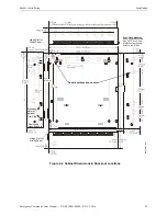
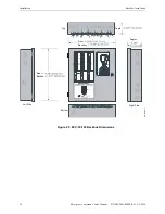
1. Mark and predrill hole in the wall for the center top keyhole mounting bolt using the dimen-
sions illustrated in Figure 2.4 on page 29.
2. Install center top fastener in the wall with the screw head protruding.
3. Place backbox over the top screw, level and secure.
4. Mark and drill the left and right upper and lower mounting holes.
Note: Outer holes (closest to sidewall) are used for 16” O.C. stud mounting.
5. Install remaining fasteners and tighten.
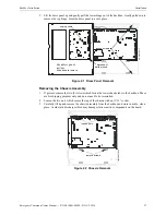
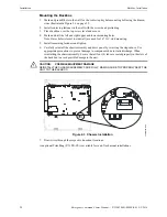
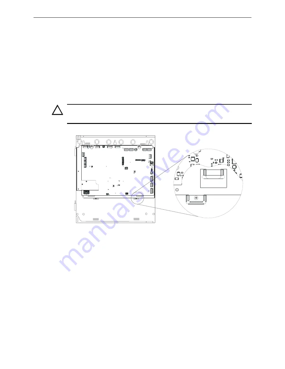
6. Carefully reinstall the chassis assembly and dress panel by reversing the steps above. Use
appropriate precautions to prevent damage to components due to static discharge. When
reinstalling the chassis assembly, be sure that all four (4) tabs are seated properly in the slots of
the backbox to avoid possible damage to the unit.
7. Draw wires through the respective knockout locations.
An optional Trim Ring (P/N TR-CE) is available for semi-flush mount installations.
!
CAUTION:
POSSIBLE EQUIPMENT DAMAGE
REINSTALL THE CHASSIS ASSEMBLY CAREFULLY, MAKING SURE TO PROPERLY SEAT THE
UNIT TO THE BACKBOX.
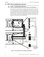
J12
TB15
J9
RTZM
Rev.
ECC-MCB-PCA
Figure 2.3 Chassis Installation
ch
assista
b
.wmf
Summary of Contents for ECC-50/100
Page 83: ...Emergency Command Center Manual P N LS10001 000FL E G 5 3 2016 83 Notes ...
Page 95: ...Emergency Command Center Manual P N LS10001 000FL E G 5 3 2016 95 Notes ...
Page 102: ...102 Emergency Command Center Manual P N LS10001 000FL E G 5 3 2016 Notes ...
Page 106: ...106 Emergency Command Center Manual P N LS10001 000FL E G 5 3 2016 Slide in Labels ...
Page 108: ...108 Emergency Command Center Manual P N LS10001 000FL E G 5 3 2016 Slide in Labels ...
Page 114: ...Cut along dotted line ...


