ECOMAX · Edition 10.17
60
Project planning information for indirect heating
Project planning information for indirect heating
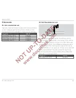
7 .12 Condition on delivery
The position of the gas, air and flue gas connections
can be customized depending on how the burner is to
be installed on the furnace. The positions of the con-
nections are coded using the numbers 0, 3, 6 and 9.
Code
Connection position
0
top
3
right-hand side
6
bottom
9
left-hand side
The codes relating to the positions of the connections
are specified in the following order: flue gas – air – gas –
and cooling air (increased furnace cooling) if required.
Provided that there are no specifications, the burners
are supplied as follows:
ECOMAX../R for indirect heating with connector posi-
tion 066, i.e. with flue gas connection at the top and
gas and air connection at the bottom.
0
3
6
9
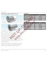
Add-on components with the marking /E, such as the
air flow detector set, UV adapter, purge air nozzle, etc,
are installed on the burner at the factory, provided that
they are ordered at the same time as the burner.
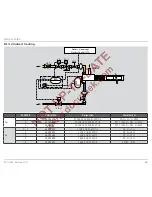
7 .13 Increased furnace cooling with
ECOMAX . .K
VR..N
VG..L
BCU 465..C
12
23
DI
L1, N, PE
µC
P
22
4
19
18
17
16
A
P
5
3
DI
6
26
GEH
EKO
32
33
VG
PLC
Depending on the technical requirements for the pro-
cess, cooling can be implemented in two stages.
▼


