background image

Re
Ju

St

As

Pr

Pr

St

1

2

3

4

5


evision 2.0 

uly 2015 

Config

tep 

Enter S

Select 
Functio

Select 
Burnou
Functio

Exit Co


ssign Temp

This se

reliminary S


The co


The us

rocedure 

tep 

Enter S

Select 
Mode 

Select 
(

UNIT

)’ 

Parame

Change
value 

Exit Co


ED

guring Downs

Action 

Set Up Mode 

‘Burnout(

BRN

)

on Parameter 

‘Downscale 

ut(

DOWN

)’ 

on Parameter 

onfiguration 

perature Uni

ection describ

Steps 

ontroller is in t

ser has the acc

Action 

Set Up Mode 

Option Set Up

‘Temp Unit 

Function 

eter 

e the ‘Temp U

onfiguration 

DC201 / EDC2

cale Burnout 

Long pre

)’ 

Long pre
without a
more tha

es the procedu

the Configura

cess to set para

Long p

Unit’ 

Long p
withou
operat


202 / EDC203

Mode 

Press 

ess 


 or 

ess 

any key operat

an 30s.  

ure of configu

ation Mode.  

ameters. 

Press 

press 


 or 

press 

ut any key 

tion more than

3 Product Man

Top D
Grou

Uppe

Uppe

Lowe


Lowe

or 

tion 

The c
return

uring Tempera


Top 
Grou

Uppe

Top 

Uppe


Lowe

 or 

n 30s. 

The 
and 

3.1

ual

R

Display= INP (

p title) 

er Display=

TYP

er Display=


BR

er Display= the

er Display=


DO

controller exits

ns to the Norm

ature Unit. 

R

Display= INP 

up title) 

er Display=

TYP

Display= OPT

er Display=


UN

er Display

in

controller exits

returns to the 

3. C

0. Configuring

Result 

(This is the firs

PE


RN


e current Burn

OWN


s Configuration

mal Operation 

Result 

(This is the fir

PE


NIT


ntended Temp 

s Configuratio

Normal Opera

Configuration

g Analog Inpu

45

st Set Up 

nout mode 

n Mode and 

Mode. 

rst Set Up 

 Unit


on Mode 

ation Mode. 


Summary of Contents for EDC 200 Series

Page 1: ...EDC201 EDC202 EDC203 Product Manual 51 52 25 155 Revision 2 0 July 2015 ...

Page 2: ...nd makes no express warranties except as may be stated in its written agreement with and for its customers In no event is Honeywell liable to anyone for any indirect special or consequential damages The information and specifications in this document are subject to change without notice Honeywell PlantScape Experion PKS and TotalPlant are registered trademarks of Honeywell International Inc Other ...

Page 3: ...s Controller Revision History EDC201 EDC202 EDC203 Product Manual Document 51 52 25 155 Rev 1 0 June 2015 First release Rev 2 0 July 2015 7 segment code added Reference The following list identifies publications that may contain information relevant to the information in this document Document Name Document ID EDC 200 Series New Wave Controllers Quick Start 51 52 25 156 EDC 200 Series New Wave Con...

Page 4: ...ntact details see back page or refer to the appropriate Honeywell Solution Support web site Honeywell Corporate www honeywellprocess com Honeywell Process Solutions https www honeywellprocess com en US explore products instrumentation panel mounted controllers and programmers Training Classes http www honeywellprocess com en US training Telephone and Email Contacts Area Organization Phone Number U...

Page 5: ... LIVE voltage be accessible RD Danger of ay be sensitiv sensitive devic arth PE term rth green or g 3 Product Man ument to deno Definition ormation that nts for the use L Identifies an bookset L Identifies an kset if not avoided em being dama erate the proce entially hazard or or moderate ctices equipment refe mation The sy manual tentially hazar rious injury or equipment ref mation The sy manual ...

Page 6: ...oduc Defin erminal Used rovement NOT e Earth at the lectrical code ctional earth bonded to Pro e with nationa dentifies a con be bonded to e with nationa ct Manual nition for non safety TE This conn source of sup requirements connection otective Earth al and local ele nnection to the Protective Ea al and local ele y purposes su nection shall b pply in accorda NOTE This at the source ectrical code ...

Page 7: ...retation 10 Instruction 10 2 4 Control and Alarm Relay Contact Information 11 Control Relays 11 2 5 Mounting 11 Physical Considerations 11 Overall Dimensions 11 Panel Cutout Requirements 12 Mounting Method 13 Mounting Procedure 13 2 6 Wiring 14 Electrical Considerations 14 2 7 Wiring Diagrams 16 Identify Your Wiring Requirements 16 Wiring the Controller 16 3 CONFIGURATION 17 3 1 Overview 17 3 2 Co...

Page 8: ... Position Step Control 48 Configuring Soft Start 49 3 12 Configuring Alarm 50 Configuring PV Alarm 50 Configuring Deviation Alarm 51 Configuring Output Alarm 53 Configuring Manual Mode Alarm 55 Configuring PV Rate of Change Alarm 56 Configuring Digital Input Alarm 57 Configuring TC Warning Alarm 58 Configuring TC Failing Alarm 59 Configuring Failsafe Alarm 60 Configuring Diagnostic Alarm 61 Assign...

Page 9: ...edure 76 4 7 Setting Parameter Mask 77 4 8 Reseting to Factory Default 78 4 9 Testing Display 78 4 10 Setting Power Frequency 79 4 11 Setting Decimal Point Location 80 4 12 Examing Product Information 80 4 13 Acknowledge Alarms 81 4 14 Setting Auto Tuning 82 Initiating Auto Tuning 82 Starting Through Keypad 82 Stopping Auto Tuning 84 4 15 Switch Manual Auto Mode 84 Preliminary Steps 84 Procedure 8...

Page 10: ...anual Revision 2 0 July 2015 5 TROUBLESHOOTING SERVICE 88 5 1 Troubleshooting Aids 88 5 2 Power up Tests 89 5 3 Background Tests 89 Diagnose System Error 89 Confirm System Error 90 6 APPENDIX A LOOK UP TABLE FOR 7 SEGMENT CHARACTER AND ASSOCIATED ENGLISH WORD 91 ...

Page 11: ... 3 Function of Keys 5 Table 2 1 Condensed Specifications 8 Table 2 2 TC RTD Types and Scope 8 Table 2 3 Environmental and Operating Conditions 9 Table 2 4 Model Number Interpretation 10 Table 2 5 Permissible Wiring Bundling 15 Table 3 1 Set Up Parameter Reference 40 Table 4 1 Lower Display Key Parameter Prompts 73 Table 4 2 Diagnostic Messages 73 Table 6 1 7 Segment Character and Associated Englis...

Page 12: ...Figure 1 2 EDC202 Operator Interface 3 Figure 1 3 EDC203 Operator Interface 4 Figure 2 1 Overall Dimensions 11 Figure 2 2 Panel Cutout Requirements 12 Figure 2 3 Composite Wiring Diagram Figure 16 Figure 3 1 Configuration Prompt Hierarchy 18 Figure 4 1 Operator Interface EDC201 EDC202 71 Figure 4 2 Operator Interface EDC203 72 ...

Page 13: ...ers plastic processing machines furnaces and ovens and packaging machinery Characteristic Input Type One analog input The analog input supports thermocouples TC or resistive temperature detector RTD two input method Analog Input accuracy 0 5 One digital input The digital input supports external dry contacts or isolated solid state contacts Output Type One control output Electromechanical relay out...

Page 14: ...he controller e controller T he limits allow ly 0 to 100 he final contro nd the target S Figure 1 1 DC203 Produc our process an tuning is initia output level i The percent ou wed by the outp for a time pro l output autom Set Point value EDC201 O ct Manual nd automatic i ated by the use n the Manual utput may be c put value The oportioning ou matically using es perator Inte identification er at the...

Page 15: ...Re Ju evision 2 0 uly 2015 ED 1 2 3 4 DC201 EDC2 Figu 202 EDC203 re 1 2 EDC2 3 Product Man 202 Operato ual or Interface 1 5 6 Introduction 1 1 Overview 3 n w 3 ...

Page 16: ...on mode sele tem temperatu tatus of extern control mode specific inform e 1 3 Functio erating mode on mode the s erating mode on mode sele C203 Opera ct Manual perator Inte it is not displa ected Set Up G ure unit nal output aut Refer to Tabl mation n of Keys for s the 4 digit cur selected para the 4 digit Set ected paramet ator Interface erface ayed Group Name is to tuning alar le 1 2 Functio spe...

Page 17: ... on the ope g press the ke ress the key to the menu item ort press the k ress the key to selected para e selected par ort press the k ress the key to Auto Tuning w Table 1 3 3 Product Man r on the operat ble status of ex ble status of a al or Auto con o control mod al or Auto con en M is on A f Alarm1 The f Alarm2 The EDC203 tion of LED erator interface ey to enter the o switch back t ms key to sw...

Page 18: ...pretation become familiar with your model selection then proceed with installation Pre installation Information If the controller has not been removed from its shipping carton inspect the carton for damage then remove the controller Inspect the unit for any obvious shipping damage and report any damage due to transit to the carrier Make sure a bag containing mounting hardware is included in the ca...

Page 19: ...cations Inputs Input Type TC E J K Platinel II Ni Ni Moly R S T RTD PT100 PT100 Low Input Sampling Time TC 250ms RTD 350ms Control Relay output Dry contact NO 5A 30 VDC or 250 VAC SSR Driver Output 24VDC 20 mA Algorithm ON OFF Time proportioning TPSC Alarm Outputs Dry contact NO 5A 30 VDC or 250 VAC Mode PROCESS VARIABLE DEVIATION OUTPUT CONTROL MODEALARM PV RATE OF CHANGE DIGITAL INPUT THERMOCOUP...

Page 20: ...ive EN 61010 1 2010 Both are Self Declared UL ANSI UL 61010 1 Third Edition CSA CAN CSA C22 2 No 61010 1 12 Third Edition Table 2 1 Condensed Specifications TC RTD Types and Scope Units C TC E Thermocouple High 270 to 1000 J Thermocouple High 18 to 871 K Thermocouple High 18 to 1316 Ni Ni Moly Thermocouple High 0 to 1371 Platinel II Thermocouple High 0 to 1380 R Thermocouple 18 to 1704 S Thermocou...

Page 21: ...55 C 32 to 131 F 40 to 66 C 40 to 151 F Relative Humidity 10 to 55 10 to 90 5 to 90 5 to 95 IP or NEMA Rating Front Panel IP54 NEMA 3R Vibration Frequency Hz Acceleration g 0 0 0 to 200 0 6 0 to 200 0 5 Mechanical Shock Acceleration g Duration ms 0 0 5 30 5 30 20 30 Table 2 3 Environmental and Operating Conditions ATTENTION The maximum moisture rating only applies up to 40 C 104 F For higher tempe...

Page 22: ...estricted availability A letter denotes restricted availability Key Numbers Table I Table II E D C 2 0 _ _ _ _ _ _ KEY NUMBER Description Selection Availability Size 48 x 48 mm 1 16 DIN 1x AI 1x ALM 1x DI EDC201 48 x 96 mm 1 8 DIN 1x AI 2x ALM 1x DI EDC202 96 x 96 1 4 DIN 1x AI 2x ALM 1x DI EDC203 Table I Power 100 240 VAC Power 24 VDC Power 0 _ _ 1 _ _ Control Output Relay Dry Contact N O 5A 30 V...

Page 23: ... is energized when output state is on 2 5 Mounting Physical Considerations The controller can be mounted on either a vertical or tilted panel using the mounting kit supplied Adequate access space must be available at the back of the panel for installation and servicing activities Overall dimensions and panel cutout requirements for mounting the controller are shown in Figure 2 2 Panel Cutout Requi...

Page 24: ...2 Installation 2 5 Mounting 12 EDC201 EDC202 EDC203 Product Manual Revision 2 0 July 2015 Panel Cutout Requirements Figure 2 2 Panel Cutout Requirements ...

Page 25: ...It will help later when selecting the proper wiring configuration Mounting Procedure 1 Orient the case properly and slide it through the panel hole from the front 2 Insert the prongs of the clips into the two holes on the left and right side of case 3 Tighten screws to secure the mounting kit against the panel CAUTION Over tightening will cause mounting kit damage and a loose fit will result in im...

Page 26: ... 100 240 Vac to an instrument rated for 24 Vdc will severely damage the instrument and is a fire and smoke hazard When applying power to multiple instruments make certain that sufficient current is supplied Otherwise the instruments may not start up normally due to the voltage drop caused by the in rush current Control Alarm Circuit Wiring The insulation of wires connected to the Control Alarm ter...

Page 27: ...undling Bundle No Wire Functions 1 Line power wiring Earth ground wiring Line voltage control relay output wiring Line voltage alarm wiring 2 Analog signal wire such as Input signal wire thermocouple 4 to 20 mA etc 4 20 mA output signal wiring Digital input signals 3 Low voltage alarm relay output wiring Low voltage wiring to solid state type control circuits Low voltage wiring to open collector t...

Page 28: ...iagrams for wiring your controller refer to the model number interpretation in this section The model number of the controller is on the outside of the case Wiring the Controller Figure 2 3 Composite Wiring Diagram Figure Callout Details 1 AC Line Voltage Terminals 2 Alarm Terminals 3 Control Input Terminals 4 TC RTD Input Terminals 5 Reserved Terminals 6 Switching Value Terminals ...

Page 29: ...nces to select and establish configure pertinent control data best suited for your application To assist you in the configuration process there are prompts that appear in the top upper and lower displays These prompts let you know what group of configuration data Set Up prompts you are working with and also the specific parameters Function prompts associated with each group ...

Page 30: ...3 Configuration 3 2 Configuration Prompt Hierarchy 18 EDC201 EDC202 EDC203 Product Manual Revision 2 0 July 2015 3 2 Configuration Prompt Hierarchy Figure 3 1 Configuration Prompt Hierarchy ...

Page 31: ... prompt Enters v after ano The con returns t 3 ual gured at the fac ow the below p y associated F Re play INP Th tle Display TYPE tially displays own in the pro figuration Pro Up group title meters you wa d to the next st Display the fi hat Set Up gro Display the c irst function pr p tially displays s of the Set Up d Stop at the f change then ents or decrem n that appears value or select other key...

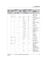
Page 32: ...on Top Display Upper Display Lower Display Input TYPE TYPE Disable Disable DISB Disabled E EH E Thermocouple High J JH J Thermocouple High N NNMH Ni Ni Moly Thermocouple High KH KH K Thermocouple High P PLH P Thermocouple R R R Thermocouple S S S Thermocouple T TH T Thermocouple High PT100 100 100 Ohm RTD High PT100 Low 100L 100 Ohm RTD Low Rhi ANH 100 999 9999 100 Input high range value Input hig...

Page 33: ...ding table automatically depending on the input type It cannot be modified RATIO RATO 1 20 00 20 00 Ratio on input BIAS BIAS 0 999 9999 Bias is used to compensate the input for drift of an input value due to deterioration of a sensor or some other cause Select the Bias value you want on the Input FILTER FILT 0 0 120s A software digital filter is provided for the Input to smooth the input signal 0 ...

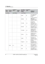
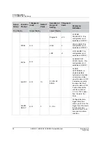
Page 34: ... fails The maximum permissible PV value shall be The maximum value Ratio High Range 1 of range span Bias Which shall not be greater than High Range 10 of range span DOWN DOWN DOWNSCALE BURNOUT will force the Input signal to the lower range value when the sensor fails The minimum permissible PV value shall be The minimum value Ratio Low Range 1 of range span Bias Which shall not be less than Low Ra...

Page 35: ... Code Default Value Selection or Range of Setting 7 Segment Code Parameter Definition Top Display Upper Display Lower Display Control CTL ALG ALGC ON OFF ON OFF ONOFF The difference PV SP of Process Variable PV and the Set Point SP determines the output The output can be either ON 100 or OFF 0 In direct acting control when the error signal is positive the output is 100 and when the error signal is...

Page 36: ...n Top Display Upper Display Lower Display Time B TImB Proportional Output based on PID B has a resolution of 3 33 msec Cycle Time is adjustable from 1 to 120 seconds Unlike the PID A equation the controller gives only an integral response to a setpoint change with no effect on the output due to the gain or rate action and it gives full response to PV changes Otherwise controller action is as descr...

Page 37: ...motor driven by two controller relay outputs The Three Position Step Control algorithm provides an output display OUT which is an estimated motor position since the motor is not using any slidewire feedback Although this output indication is only an approximation it is corrected each time the controller drives the motor to one of its stops 0 or 100 CYC Time CYCT 1 1 120 Cycle time used for time pr...

Page 38: ...s output decreases as the process variable increases Direct DIRT DIRECT ACTING CONTROL Based on the PID control the controller s output increases as the process variable increases RLYSTATE RLST OFF OFF OFF It is used for controlling the digital output Digital output de energizes when the control output is 0 ON ON It is used for controlling digital output Digital output energizes when control outpu...

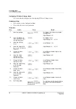
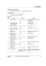
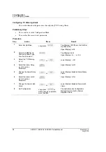
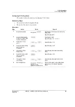
Page 39: ...etween the value of the process variable at which the control outputs energize and the value at which they de energize ATTENTION Only applicable for ON OFF control DEADBAND DB 1 0 5 5 0 DEADBAND is an adjustable gap between the operating ranges of output 1 and output 2 in which neither output operates positive value or both outputs operate negative value Apply to TPSC FAILMODE FLMD Latch Latch LA ...

Page 40: ...l Algorithm This is the time it takes the motor to travel from 0 to 100 fully closed to fully open This time can usually be found on the nameplate of the motor Soft Start SFST DISABLE DISABLE DISB Disable the soft start feature ENABLE EABL Enable the soft start feature Output Limit CLIM 0 0 100 Soft Start Output Power Limit is the limit output applied to the heater or the machine at power up Set P...

Page 41: ...you are using so that your controller responds correctly to changes in process variable and Set Point You can start with predetermined values but you will have to watch the system to see how to modify them The Accutune feature automatically selects Gain Rate and Reset on demand ATTENTION Because this group contains functions that have to do with security and lockout we recommend that you configure...

Page 42: ...the two Set Points to alarm on the same event and to alarm both high and low A single adjustable Hysteresis of 0 to 100 is configurable for the alarm Set Point The prompts for the Alarm Outputs appear whether or not the alarm relays are physically present This allows the Alarm status to be shown on the display Function Prompts Set up Group Function Prompt 7 Segment Code Default Value Selection or ...

Page 43: ... PROCESS VARIABLE DEV DEV DEVIATION Output OUT OUTPUT MANUAL Man ALARM ON MANUAL MODE PV RATE PVRT PV RATE OF CHANGE DIG INP DIN DIGITAL INPUT TCWARN TCWN THERMOCOUPLE WARNING TCFAIL TCFL THERMOCOUPLE FAILING FSAFE FS FAILSAFE Diagnostic DIAG SYSTEM DIAGNOSTIC 12SEL SE12 HIGH HI HIGH ALARM LOW LO LOW ALARM 12VAL VL12 ALARM 12 SET POINT VALUE 21TYPE AL21 None NONE This configuration is not availabl...

Page 44: ...DC201 PV RATE PVRT PV RATE OF CHANGE This configuration is not available on EDC201 DIG INP DIN DIGITAL INPUT This configuration is not available on EDC201 TCWARN TCWN THERMOCOUPLE WARNING This configuration is not available on EDC201 TCFAIL TCFL THERMOCOUPLE FAILING This configuration is not available on EDC201 FSAFE FS FAILSAFE This configuration is not available on EDC201 Diagnostic DIAG SYSTEM ...

Page 45: ...V PV This configuration is not available on EDC201 DEV DEV DEVIATION This configuration is not available on EDC201 Output OUT OUTPUT This configuration is not available on EDC201 MANUAL Man ALARM ON MANUAL MODE This configuration is not available on EDC201 PV RATE PVRT PV RATE OF CHANGE This configuration is not available on EDC201 DIG INP DIN DIGITAL INPUT This configuration is not available on E...

Page 46: ...DC201 LOW LO LOW ALARM This configuration is not available on EDC201 22VAL VL22 ALARM 22 SET POINT VALUE This configuration is not available on EDC201 ALHYST HYSA 1 0 100 OF SPAN ALARM HYSTERESIS A single adjustable hysteresis is provided on alarms such that when the alarm is OFF it activates at exactly the alarm Set Point when the alarm is ON it will not deactivate until the variable is 0 0 to 10...

Page 47: ...Alarm output is configured to be Non latching When an alarm condition is met the alarm is triggered when the alarm condition is cleared the alarm is automatically reset BLOCK BLK DISABLE DISABLE DISB Disables alarm blocking ALARM1 ALM1 Blocks Alarm 1 only ALARM2 ALM2 Blocks Alarm 2 only This configuration is not available on EDC201 ALARM12 AM12 Blocks both alarms This configuration is not availabl...

Page 48: ...lue Selection or Range of Setting 7 Segment Code Parameter Definition Top Display Upper Display Lower Display ALARM2 ALM2 START allows you to select whether the timer starts with the Alarm 2 This configuration is not available on EDC201 PERIOD PERI 0 00min 9 59hrs PERIOD allows you to configure the length of the timeout period from 0 to 9 hours 59 minutes ...

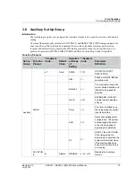
Page 49: ...Function Prompt 7 Segment Code Default Value Selection or Range of Setting 7 Segment Code Parameter Definition Auxiliary DIG IN DIN None NONE NONE NO DIGITAL INPUT SELECTIONS A M AM Switch Automatic Manual operating mode Direction DIR The controller will scan the current action direction and redirect to the opposite direction LOCK LOCK KEYBOARD LOCKOUT Contact closure disables all keys Timer TMR T...

Page 50: ...0HZ Power Frequency 60HZ 60HZ Power Frequency DECIMAL DECI None None NONE No Decimal Place One 1 1 decimal place ATTENTION Auto ranging will occur for selections of one two or three decimal places For example should the instrument be configured for two decimal places and the PV exceeds 99 99 then the display will change to a single decimal place so that values of 100 0 and above can be shown Two 2...

Page 51: ... GF D VN F VN H CD E ST T FT R o F NE D SP L w 3 C 3 9 OPTION Parameter Definition 3 decimal plac ATTENTION A will occur for s one two or thr places For ex he instrument for two decima he PV exceed he display wil single decimal values of 100 0 can be shown Degrees Celsi Degrees Fahre Firmware vers Hardware vers Error code Testing LED d Restoring the c of the instrume Factory Setting Disable the Lo...

Page 52: ...s for operator level Lower display shows LOCK if a key is pressed Long press Setup key and input the Configurator level password to unlock keys OPERATI NG LEVEL OPLV None Oper OPER Operator level CFG CFG Configuration level Mask MASK Customizing parameter mask Determine the hide unhide and configurable unconfigurable features for different operation levels PASSWO RD PASS Oper OPER Setting the oper...

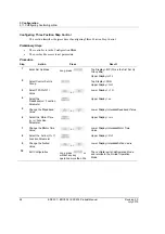
Page 53: ...ong TC n ion n able atio AS if as if Long witho more 202 EDC203 Input ure of configu ation Mode ameters Press press or or or press ut any key op than 30s 3 Product Man uring TC Type Top Gro Up Low Up Low Hig Ack Up Low Low Ack Up Low Inp Up Low Inp Up Low Inp or eration The and Mo 3 1 ual e Input includ p Display INP oup title per Display T wer Display in per Display wer Display t gh Range knowled...

Page 54: ...f ation EDC202 ED procedure of c lter nfiguration M set parameters Pr Long press or or or Long press without any more than 3 DC203 Produc configuring R Mode s ress r r r or key operation 0s ct Manual RTD Type Inpu Top Disp Up Grou Upper Di Lower Di Upper Di Lower Di RTD Hig Acknowle Upper Di Lower Di RTD Low Acknowle Upper Di Lower Di RTD Inpu Upper Di Lower Di RTD Inpu Upper Di Lower Di RTD Inpu ...

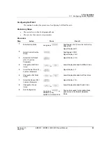
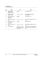
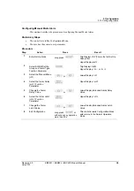
Page 55: ...rnout es the procedu the Configura cess to set para fe Mode Long ction Up F e de e cable Long with more 202 EDC203 ure of configu ation Mode ameters Press g press or or or g press out any key o e than 30s 3 Product Man uring Burnout T U U U L m L T U L U L or peration T a M 3 1 ual Mode for An Top Display I Up Group title Upper Display Upper Display Lower Display mode Lower Display Top Display C U...

Page 56: ...e than 30 out Mode Press Long press or Long press without any ke more than 30s DC203 Produc ess or ey operation s s or y operation ct Manual Top Displa Group title Upper Dis Upper Dis Lower Dis Lower Dis The contro and return Mode Top Display Group title Upper Displa Upper Displa Lower Displa Lower Displa The controlle returns to th Result ay INP This e splay TYPE splay BRN splay the curr splay NO...

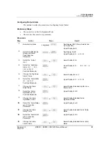
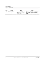
Page 57: ...a Long p p Unit Long p withou operat 202 EDC203 Mode Press ess or ess any key operat an 30s ure of configu ation Mode ameters Press press or press ut any key tion more than 3 Product Man Top D Grou Uppe Uppe Lowe Lowe or tion The c return uring Tempera Top Grou Uppe Top Uppe Lowe or n 30s The and 3 1 ual R Display INP p title er Display TYP er Display BR er Display the er Display DO controller exi...

Page 58: ...t S ameter Output alue nimum On Function Minimum ue elay Function Relay State ation EDC202 ED ntrol Algo procedure of c nfiguration M set parameters Press Long press or or or Long press without any more than 3 DC203 Produc orithm configuring C Mode s r r r or key operation 30s ct Manual ontrol Algorit Result Top Disp Up Grou Upper Di Top Disp Upper Di Lower Di Upper Di Lower Di Hysteres Upper Di L...

Page 59: ...2 rtion Contro es the procedu the Configura cess to set para Long Up or n State CTN Long witho more 202 EDC203 ol ure of configu ation Mode ameters Press press or or or or press out any key op e than 30s 3 Product Man uring Time Pro or peration 3 11 Co ual oportion Cont Top Display Up Group title Upper Displa Top Display Upper Displa Lower Displa Upper Displa Lower Displa Value Upper Displa Lower ...

Page 60: ...d otor Time on Motor Time ction ACTN ameter Action ation EDC202 ED ep Control procedure of c nfiguration M set parameters Pre Long press or or or or Long press without any operation m DC203 Produc configuring Th Mode s ess r r r r or key ore than 30s ct Manual hree Position Top Displa Group title Upper Dis Top Displa Upper Dis Lower Dis Upper Dis Lower Dis Upper Dis Lower Dis Value Upper Dis Lower...

Page 61: ... the Configura cess to set para Long Up t rt SP nt ERI Long witho opera 202 EDC203 ure of configu ation Mode ameters Press press or or or press out any key ation more tha 3 Product Man uring Soft Star Top Gro Up Top Up Up Low Up Low Up Low or an 30s The and Mo 3 11 Co ual rt functon p Display INP oup title per Display T p Display CO per Display A per Display S wer Display in per Display S wer Disp...

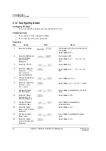
Page 62: ...rm describes the p r is in the Con the access to s n Mode L M Set Up arm n V PV gh Low SE12 ameter High Low arm Set L12 Alarm ue arm YSA ameter Alarm alue arm Function Alarm arm Function EDC202 ED rm procedure of c nfiguration M set parameters Pres Long press or or or or or DC203 Produc configuring PV Mode s ss ct Manual V Alarm Top Displa Group title Upper Dis Top Displa Upper Dis AL22 Lower Dis ...

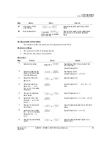
Page 63: ... Long pr without more th larm es the procedu the Configura cess to set para Long Up ype tion w t L21 Set ate ction State 202 EDC203 Press or ress any key opera an 30s ure of configu ation Mode ameters Press g press or or or or 3 Product Man Low Va or ation The and Mo uring Deviatio To U U To U Lo U AM Lo U Lo Va U Lo Al ual wer Display in lue e controller ex d returns to th ode on Alarm op Display...

Page 64: ...alue arm Delay on Alarm Delay arm Latch on Alarm Latch ation EDC202 ED Pr o o o Long press without any more than 3 DC203 Produc ress or or or s or y key operatio 30s ct Manual Upper Di Lower Di Hysteres Upper Di Lower Di Value Upper Di Lower Di Value n The cont and retur Mode Resul isplay HYSA isplay intende sis Value isplay DLYA isplay intende isplay LACH isplay intende troller exits Co rns to th...

Page 65: ... Value the Alarm De Function eter e the Alarm Value the Alarm La Function eter e the Alarm Value DC201 EDC2 m es the procedu the Configura cess to set para Long p Up w ow ate elay tch 202 EDC203 ure of configu ation Mode ameters Press press or or or or or or 3 Product Man uring Output A To U U To U Lo U AM Lo U Lo Al U Lo Hy U Lo Va U Lo Va ual Alarm op Display IN p Group title pper Display op Dis...

Page 66: ...io Exit Configura m EDC201 n ation EDC202 ED Pre Long press without any k more than 30 DC203 Produc ess or ey operation s ct Manual The cont and retur Mode Resul troller exits Co rns to the Norm Revis Ju lt onfiguration M mal Operation sion 2 0 ly 2015 ode n ...

Page 67: ... EDC2 de Alarm es the procedu the Configura cess to set para Long Up ype Mode elay tch Long witho more 202 EDC203 ure of configu ation Mode ameters Press press or or or press ut any key op than 30s 3 Product Man uring Manual Top Gro Up Top Up Low Up Low Va Up Low Va or eration The and Mo ual Mode Alarm p Display INP oup title per Display T p Display AL per Display A wer Display per Display D wer D...

Page 68: ...m YSA ameter Alarm alue arm Delay on Alarm arm Latch on Alarm ation EDC202 ED e Alarm procedure of c nfiguration M set parameters Pr Long press or or or or or Long press without any more than 3 DC203 Produc configuring PV Mode s ress r r r r r or key operation 0s ct Manual V Rate of Cha Top Dis Up Grou Upper D Top Dis Upper D Lower D Upper D Lower D Alarm V Upper D Lower D Hystere Upper D Lower D ...

Page 69: ...DC201 EDC2 t Alarm es the procedu the Configura cess to set para Long Up ype put ate ction elay atch Long witho more 202 EDC203 ure of configu ation Mode ameters Press press or or or or or press ut any key op than 30s 3 Product Man uring Digital I To U U To U Lo U Lo Al U Lo Hy U Lo Va U Lo Va or eration Th an M ual Input Alarm op Display IN p Group title pper Display op Display A pper Display owe...

Page 70: ...C Warning arm Delay on Alarm Delay arm Latch on Alarm Latch ation EDC202 ED m procedure of c nfiguration M set parameters P Long press o o o Long press without any more than 3 DC203 Produc configuring TC Mode s Press r r r or key operation 30s ct Manual C Warning Al Top Di Up Gro Upper Top Di Upper Lower Upper Lower Value Upper Lower Value n The co Mode a Operat larm Resu isplay INP T oup title Di...

Page 71: ...01 EDC2 Alarm es the procedu the Configura cess to set para Long Up ype elay tch Long witho opera 202 EDC203 ure of configu ation Mode ameters Press press or or or press out any key ation more tha 3 Product Man uring TC Fail Top Gro Up Top Up Low Up Low Va Up Low Va or an 30s The and Mo ual Alarm p Display INP oup title per Display T p Display AL per Display A wer Display per Display D wer Display...

Page 72: ...n Mode M Set Up arm Type ameter ilsafe FS arm Delay on Alarm arm Latch on Alarm ation EDC202 ED procedure of c nfiguration M set parameters Pres Long press or or or Long press without any k operation mo DC203 Produc configuring Fa Mode s ss or key re than 30s ct Manual ailsafe Alarm Top Display Group title Upper Disp Top Display Upper Disp Lower Disp Upper Disp Lower Disp Value Upper Disp Lower Di...

Page 73: ...EDC2 Alarm es the procedu the Configura cess to set para Long Up ype ic elay tch Long witho opera 202 EDC203 ure of configu ation Mode ameters Press press or or or press out any key ation more tha 3 Product Man uring Diagnos Top Gro Up Top Up Low Up Low Va Up Low Va or an 30s The and Mo ual stic Alarm p Display INP oup title per Display T p Display AL per Display A wer Display per Display D wer Di...

Page 74: ... Up arm Type ameter arm Type arm YSA ameter Alarm alue ation EDC202 ED procedure of c nfiguration M set parameters ort hysteresis a Pres Long press or or Long press without any k operation mo DC203 Produc configuring A Mode s assignment ss or key re than 30s ct Manual Alarm Hysteres Top Display Group title Upper Disp Top Display Upper Disp Lower Disp Value Upper Disp Lower Disp Value The control a...

Page 75: ...201 EDC2 y es the procedu the Configura cess to set para Long p Up elay Long p withou more t 202 EDC203 ure of configu ation Mode ameters Press press or press t any key ope han 30s 3 Product Man uring Alarm D Top Grou Upp Top Upp Upp Low Valu or ration The and Mod ual Delay Display INP up title per Display TY Display ALM per Display AL per Display DL wer Display int ue controller exit returns to t...

Page 76: ...cking describes the p r is in the Con the access to s n Mode L M Set Up arm n arm ameter EDC202 ED procedure of c nfiguration M set parameters Pre Long press or Long press without any operation m procedure of c nfiguration M set parameters Pres Long press DC203 Produc configuring A Mode s ess r or key ore than 30s configuring A Mode s ss ct Manual Alarm Latching Top Displa Group title Upper Dis To...

Page 77: ...ura cess to set para Long Up ype MR eri Long witho more 202 EDC203 Press or ress any key opera an 30s ure of configu ation Mode ameters Press press or press out any key op e than 30s 3 Product Man Low Valu or ation The and Mod uring Timer T U U T U U L U L V or peration T a M ual wer Display int ue controller exit returns to the de Top Display I Up Group title Upper Display Top Display A Upper Dis...

Page 78: ...e Con the access to s n Mode et Up igital nction NONE ation EDC202 ED ital Input procedure of d nfiguration M set parameters Pre Long press or Long press without any k more than 30 DC203 Produc t disabling DI fu Mode s ess or ey operation s ct Manual function Top Displa Group title Upper Dis Top Displa Upper Dis Lower Dis The contro and return Mode Result ay INP This e splay TYPE ay AUX splay DIG ...

Page 79: ...l Direction es the procedu the Configura cess to set para Long R Long witho opera 202 EDC203 itch ure of configu ation Mode ameters Press ress or ress any key opera an 30s Switch ure of configu ation Mode ameters Press press or press out any key ation more tha 3 Product Man uring DI as Co Top Grou Upp Top Upp Low or ation The and Mod uring DI as Co Top Gro Up Top Up Low or an 30s The and Mo 3 1 ua...

Page 80: ...DC202 ED king Switch procedure of c nfiguration M set parameters Pres Long press or Long press without any k more than 30 ing Trigger procedure of c nfiguration M set parameters Press ong press or ong press thout any key ore than 30s DC203 Produc h DI configuring D Mode s ss or ey operation s configuring D Mode s or y operation ct Manual DI as Keypad L Top Display Group title Upper Disp Top Displa...

Page 81: ...es the procedu the Configura cess to set para Long Long witho more 202 EDC203 ging Switch ure of configu ation Mode ameters Press press or press out any key op e than 30s 3 Product Man h uring DI as Al To U U To U Lo or peration Th an M 3 1 ual larm Acknowl op Display IN p Group title pper Display op Display A pper Display ower Display he controller e nd returns to t ode 3 C 13 Configurin ledging ...

Page 82: ...ess to s on Mode et Up igital nction ation EDC202 ED g Initiating T procedure of c nfiguration M set parameters Pres Long press or Long press or without an operation m 30s DC203 Produc Trigger configuring D Mode s ss r ny key ore than ct Manual DI as AT Initia Top Display Group title Upper Displa Top Display Upper Displa Lower Displa The controlle returns to th ating Trigger Result INP This is ay ...

Page 83: ...Interface ov ation mode se Interface ure 4 2 provide Figure 4 1 202 EDC203 and Ope ormation nece verview how etting the time e e the view of t Operator I 3 Product Man erating ssary to help y w to switch bet er and monitor the Operator I Interface ED ual the Co you monitor a tween normal ring the displa Interfaces DC201 EDC ntroller and operate yo operation mo ays C202 71 r our controller de and 1...

Page 84: ...tions hav A visual in A visual in On Manu Off Autom Accutunin A visual in None N F Degre C Degre DC203 Produc Operator In troller ve been provid ndication of ea ndication of the al Mode matic Mode g in progress ndication of the No temperatur es Fahrenheit ees Celsius ct Manual terface EDC ded to help mo Indication ach alarm e control relay e temperature e unit annunc t C203 onitor the con ys e uni...

Page 85: ...ured as Latch Fail Fail Failsafe conditions for failsafe are EEROM Test Failed Scratch Pad RAM Test Failed Configuration Test Failed Field or Factory Cal Test Failed Table 4 1 Lower Display Key Parameter Prompts Diagnostic Messages The EDC 200 Series performs background tests to verify data and memory integrity If there is a malfunction a diagnostic message will be shown on the lower display In th...

Page 86: ...iew and acknowledge Failsafe and Alarms Parameter Configuration In the configuration mode the configurator configures the function parameters in authorized Set up Groups and enter Mask mode Control Mode Mode Definitions Control Mode Definition AUTOMATIC with LOCAL SET POINT In automatic local mode the controller operates from the local Set Points and automatically adjusts the output to maintain th...

Page 87: ...ng pr r 202 EDC203 n Level r parameters ng the followin Press ress or 4 3 Product Man configurator l ng procedure Top D Top D Uppe Lowe Uppe Lowe Confi If n If to Monitoring a 4 ual level and oper Display OPT Display OPT er Display OP er Display OP er Display PA er Display 00 irm the input v f the password ormal operatin f you enter the o Step 4 and Operating 4 5 Setting O rator level You Result T...

Page 88: ...ller EDC202 ED ation Pas figurator level configurator le ssword can no Pres ong press or DC203 Produc ssword l for authority evel The pass ot be changed ss ct Manual management sword of opera before the ope Top Display Top Display Upper Displa Lower Displa Upper Displa Confirm the If the pas normal o If you en to Step 4 purpose or ch ator and confi erator passwo Result OPT OPT ay PASS ay OPER CFG ...

Page 89: ...nd the us Top Dis Top Dis Upper D Lower D Enter S Top Dis Upper D Lower D Note Configu case o parame Display Configu parame Monitoring a 4 ual ation by differ ithout a passw ser has the acc R splay OPT splay OPT Display OPLV Display MASK Set up Mode splay current Display curre Display Param 00 Hide the p urable only for perator could eter but could y the paramete urator level ca eters and Operatin...

Page 90: ...ameter ontroller EDC202 ED actory D procedure of r nfiguration M set parameters Pre Long press or Long press without any operation m procedure of r nfiguration M set parameters Pre Long press DC203 Produc Default resetting confi Mode s ess r or key ore than 30s resetting to Te Mode s ess ct Manual figuration to fa Top Displa Group title Upper Dis Top Displa Upper Dis Upper Dis Lower Dis All the pa...

Page 91: ... more tha uency ure of setting ation Mode ameters Press press or press out any key ation more tha 4 3 Product Man Low All ind or an 30s The and Mo Power Freque Top Gro Up Top Up Low Fre or an 30s The and Mo Monitoring a 4 10 ual wer Display the LEDs on t icate the LED e controller ex d returns to th ode ency p Display INP oup title per Display T p Display OP per Display H wer Display equency Value...

Page 92: ...ccess to s n Mode et Up STA ameter ontroller n EDC202 ED mal Point procedure of s nfiguration M set parameters Pre Long press or Long press without any operation m ct Inform procedure of e nfiguration M set parameters Pres Long press DC203 Produc t Locatio setting Decim Mode s ess r or key ore than 30s mation examing the P Mode s ss ct Manual on mal Point Locat Top Displa Group title Upper Dis Top...

Page 93: ...abled th abled In the S triggered The ged it will sto play arm 202 EDC203 Press or rms or Latching hat is LACH hat is LACH Set Up Mode e Alarm LED k op blinking if t Press 4 3 Product Man Lowe Uppe Lowe NO the ALM YES use the LACH YES keeps blinking the alarm is st Lower D If the ala blinking If alarm Monitoring a ual R er Display FW er Display FW er Display Sy M LED lights following pro S g when ...

Page 94: ...er EDC202 ED Tuning e procedure of set parameters Pre Long press or Long press without any operation m controller is c s a PID ALGC Tuning funct peration mode Pres DC203 Produc f initiating Aut s ess r or key ore than 30s onfigurator le C Time A or tion is enabled e and MAN L ss Lo A ct Manual to Tuning Top Displa Group title Upper Dis Top Displa Upper Dis Upper Dis Lower Dis The contro and return...

Page 95: ... EDC203 Product Manual 83 July 2015 System detects the rising edge of the digital input and sends the command to start the Auto Tuning process If the prerequisite of Auto Tuning is not met the lower display will show up Error ERR after short pressing otherwise the Auto Tuning process is started ...

Page 96: ... peration the lower ow the o Tuning ning ch Manua r is in the Nor on al Auto ng SP atic mode Lef level of SP va n isplay value to be set ontroller EDC202 ED Press al Auto M rmal Operatio Pres ft Display M alue Press DC203 Produc Lower If A AT If A Au Auto Mode on Mode ss Le MAN LED off Lo ct Manual Display ATS Auto Tuning is TSR Auto Tuning is uto Tuning is ru Tuning is stop eft Display M In Auto ...

Page 97: ... Man Lower Dis Short the SP Long p the SP Long p short p the sto eriod of from he Set up mod Lower Di If the Disp If the rema If the tim Lower D time is d Monitoring a ual splay current press P value press P value press press opped digit pla 0 to 9 hours de TMR ENA Re splay TX XX e timer is read play configura e timer is runn aining time is d mer is timed ou Re Display T log displayed and Operatin...

Page 98: ...es the peration Mode on SP Value or peration Mode on SP al Control PV SP Value ue or ontroller EDC202 ED Lower Display Pres Value e procedure of e MAN LED Pre o e AT LED is Pr o DC203 Produc y T 0 00 ss L f setting outpu is off and Low ess or on and Lower ress or ct Manual ower Display ut value wer Display Lower Disp Lower Disp r Display cu Lower Dis current va MAN LED Lower Dis Enters val memory ...

Page 99: ...V DC201 EDC2 n Mode Man Value 202 EDC203 LED is on an Press or 4 3 Product Man nd Upper Disp Low Up val Low OU Monitoring a ual play current P Re wer Display M per Display I ue wer Display In UT LED blinks and Operating 4 18 Setting PV Lower Dis esult MXX X Intended PV c ntended Outp the Controller g Output Value 87 splay SP current ut value r e 7 ...

Page 100: ...he Status Tests are requested During continuous background tests while in normal operation Check installation If a set of symptoms still persists refer to Section 2 Installation and ensure proper installation and proper use of the controller in the system Customer support If you cannot solve the problem using the troubleshooting procedures listed in this section you can get technical assistance by...

Page 101: ...e 202 EDC203 ion P n sion P Customer Sup rmine a soluti oller will run k Power on se lsafe mode In he diagnostic s ground tests to played in the lo se tests can be P 3 Product Man Press Press pport person I on to your pro three diagnos elf check runs n failsafe mode tests performe o verify data a ower display e checked to d Press 5 ual Upper Displ Lower Displ Upper Displ Lower Displ Upper Displ Lo...

Page 102: ...iew and troublesh re on restoring re on reading F re on reading d re on reading c re on reading v cation code Co re on reading p meter Configu cation data err Failure specific failure Failsafe mode meter values ar l Operating M Pres DC203 Produc all of the erro hooting proced Prob g factory defau FCT data digital sign configuration d verification co omparison erro product code ration error ror e y...

Page 103: ... T U V W X Y Z Table 6 1 7 Segment Character and Associated English Word 7 Segment Code Abbreviation of the Associated English Word Full Name of the Associated English Word DISB DISB DISABLE EABL EABL ENABLE FILT FILT FILTER ACTN ACTN ACTION REVR REVR Reverse DIRT DIRT Direct DB DB DEADBAND FLMD FLMD FAILMODE FLSF FLSF FAILSAFE PERI PERI PERIOD RLST RLST RLYSTATE Table 6 2 Examples for 7 Segment C...

Page 104: ...s below ASIA PACIFIC Honeywell Process Solutions TAC hfs tac support honeywell com Australia Honeywell Limited Phone 61 7 3846 1255 FAX 61 7 3840 6481 Toll Free 1300 36 39 36 Toll Free Fax 1300 36 04 70 China PRC Shanghai Honeywell China Inc Phone 86 21 5257 4568 Fax 86 21 6237 2826 Singapore Honeywell Pte Ltd Phone 65 6580 3278 Fax 65 6445 3033 South Korea Honeywell Korea Co Ltd Phone 822 799 611...

Reviews: