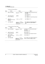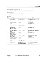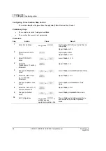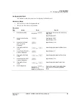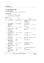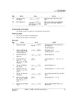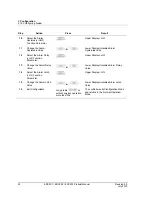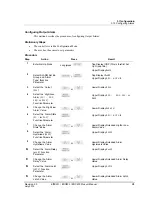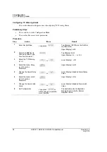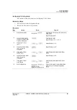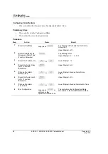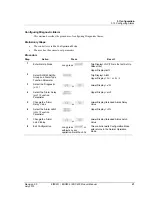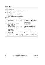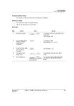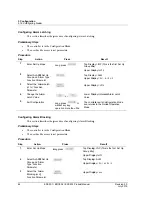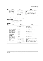
Re
Ju
Co
Pr
Pr
St
1
1
1
evision 2.0
uly 2015
onfiguring D
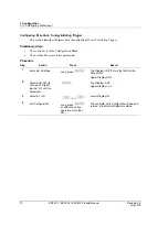
This se
reliminary S
•
The co
•
The us
rocedure
tep
1
Enter S
2
Select
Group
Functio
3
Select
(
DIG
)’
4
Select
(
AM11
o
Param
5
Chang
State’ V
6
Select
Hystere
Functio
7
Chang
Hystere
8
Select
(
DLYA
)’
Param
9
Chang
Delay’
10
Select
(
LACH
)’
Param
11
Chang
Latch’
12
Exit Co
ED
Digital Input
ection describ
Steps
ontroller is in t
ser has the acc
Action
Set Up Mode
ALARM Set U
and ‘Alarm Ty
on Parameter
the ‘Digital Inp
the ‘Alarm Sta
or
AM12
)’ Func
eter
e the ‘Alarm
Value
the ‘Alarm
esis (
HYSA
)’
on Parameter
e the ‘Alarm
esis’ Value
the ‘Alarm De
Function
eter
e the ‘Alarm
Value
the ‘Alarm La
Function
eter
e the ‘Alarm
Value
onfiguration
DC201 / EDC2
t Alarm
es the procedu
the Configura
cess to set para
Long
Up
ype’
put
ate
ction
elay
atch
Long
witho
more
202 / EDC203
ure of configu
ation Mode.
ameters.
Press
press
or
or
or
or
or
press
ut any key op
than 30s.
3 Product Man
uring Digital I
To
U
U
To
U
Lo
U
Lo
Al
U
Lo
Hy
U
Lo
Va
U
Lo
Va
or
eration
Th
an
M
ual
Input Alarm.
op Display= IN
p Group title)
pper Display=
op Display= A
pper Display=
ower Display=
pper Display=
ower Display=
larm Value
pper Display=
ower Display=
ysteresis Valu
pper Display=
ower Display=
alue
pper Display=
ower Display=
alue
he controller e
nd returns to t
ode.
3. C
3.12. Con
Result
NP (This is the
=
TYPE
ALM
=
AL11
or
AL12
=
PVRT
=
AM11
or
AM12
=intended High
=
HYSA
=intended Alar
ue
=
DLYA
=intended Alar
=
LACH
=intended Alar
exits Configura
he Normal Op
Configuration
figuring Alarm
57
e first Set
2
2
h or Low
rm
rm Delay
rm Latch
ation Mode
peration
n
m
7


