Calibration
4-6
SVP Controller Operation Manual
Part No.: 44200004 - Revision 2
Procedure
Water draw notes:
Perform steps 12-17 at least twice prior to taking data to purge the system of
air, assure the temperature is stable, and to get familiar with the procedure.
Repeat the water draw procedure until at least 3 consecutive draws
repeat within 0.02% or other repeatability criteria that the certifying parties
agree upon. The flow rate on at least one run must vary by 25% to assure
integrity of prover seals and absence of leakage.
Failure to achieve the necessary repeatability may be caused by leaking
valves, air in the system, varying pressure, leaking seals, or faulty
calibration technique.
1. Be certain that all maintenance that needs to be done to the prover
has been accomplished before starting the volumetric calibration. It
is advisable to perform a static leak test prior to performing a water
draw, see Section 4.2. Replace the seals on the prover if there is any
doubt as to their integrity.
2. Block prover inlet and outlet by using a blind flanges or double block
and bleed valves.
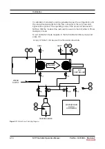
3. Refer to Honeywell Enraf water draw configuration, Figure 4-7, and
install Honeywell Enraf available water draw kit, see Figure 4-6. Install
certified thermometers and certified pressure gauge, even if the prover
is equipped with P&T transmitters.
If using Honeywell Enraf Water Draw P&T kit, remove the plug in the
wafer spacer and connect the pressure gauge P1 to the opening (see
Figure 4-7 for reference).
The thermometer used to monitor prover fluid temperature T1 is
supposed to be installed into the spare thermowell located on the
downstream side of the flow tube (see Figure 4-7 for reference).
The thermometer used to monitor switch bar temperature T2 is
supposed to be installed on top of the switch bar close to the center
line between two optical switches (see Figure 4-7 for reference).
The thermometer used to monitor test measure temperature T3
is supposed to be installed on the test measure (see Figure 4-7
for reference).
Have available Table 1 to record data from prover calibration using
volumetric water draw technique.
4. Connect water supply to prover, (refer to Figure 4-7).
5. Make sure that the water draw kit is wired to the customer connection
enclosure as specified in the Figure 4-6.
6. Turn water supply on, and open valves V1, V2, and V3. After all air is
bled off, close V2 and V3. Open V5 valve and allow water to circulate
until the temperature has stabilized and is not changing.


