NFS Supra
Page 26
HLS-MN-025 v.04
Installation and Operating Manual
www.honeywelllifesafety.es
www.hoeywelllifesafety.es
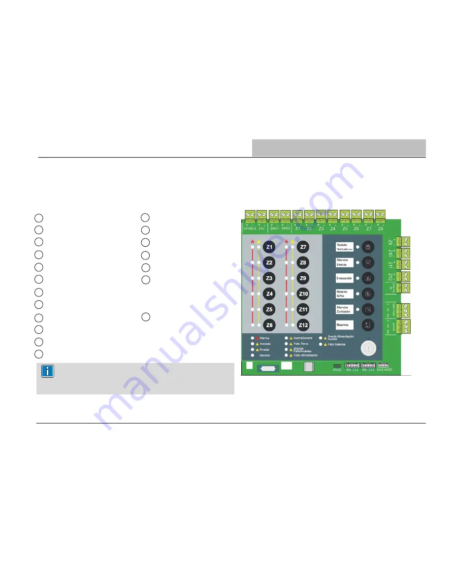
4.4 Base PCB Wiring Connections
The base PCB control panel provides the external cable/wiring connectors for the following functions.
To recognize the function of connectors easily, check the associated labels in the PCB
Inputs
Outputs
Z1
Zone 1
24 V Resettable
Z2
Zone 2
24 V Fix
Z3
Zone 3
Sounders 1
Z4
Zone 4
Sounders 2
Z5
Zone 5
*
General Fault Relay
Z6
Zone 6*
General Alarm Relay
Z7
Zone 7*
Z8
Zone 8*
Programmable input:
Z9
Zone 9*
Digital Input external contact
Z10
Zone 10*
Z11
Zone 11*
Z12
Zone 12*
Installation
9
10
11
12
1
2
3
4
5
6
7
8
13
A
B
C
D
E
F
* The number of zones depends on the panel Model.
NFS4 (Zones 1 to 4); NFS8 (Zones 1 to 8) and NFS12 (Zones 1 to 12)


