background image

Honeywell 


Heating & Cooling Appliance Controls


Title: Functional description 

S4965A3025 


Doc.: 

S4965A3025E20 


Description Sign. 

E.C.N. 

Date 

Rev.

First issue 

M.Matiasko


01-Sep-2015 


Page  

1/22


ESYS CONTROLLER 


S4965A3025 


FUNCTIONAL DESCRIPTION


$URL:: 
https://acssvn.honeywell.com/ECC/CombustionEMEA/Root/Projects/P13xxxx/P130015/HW/P
roductionFunctionalDescription/S4965A3025E20.doc                               $ 
$Revision:: 77641                                                              $ 
$Author:: Mariscak, Igor                                                       $ 
$Id:: S4965A3025E20.doc 77641 2015-08-25 12:42:50Z Mariscak, Igor              $ 


Summary of Contents for ESYS S4965A3025

Page 1: ...Rev First issue M Matiasko 01 Sep 2015 A Page 1 22 ESYS CONTROLLER S4965A3025 FUNCTIONAL DESCRIPTION URL https acssvn honeywell com ECC CombustionEMEA Root Projects P13xxxx P130015 HW P roductionFunctionalDescription S4965A3025E20 doc Revision 77641 Author Mariscak Igor Id S4965A3025E20 doc 77641 2015 08 25 12 42 50Z Mariscak Igor ...

Page 2: ...als 4 5 1 General 7 5 2 Layout 8 5 3 Technical features 9 5 3 1 Connector and connections 9 5 3 2 High Voltage Connections 10 5 3 3 Communication Connector 10 5 3 4 Low Voltage Connections 11 5 3 5 Specification 11 5 4 Timing diagram 13 5 5 Recommended peripheral devices 14 5 6 Sensors and actuators 14 5 6 1 Safety Cut off Switch 14 5 6 2 Alarm Error Led 14 5 6 3 Error Output to Esys 2 14 5 6 4 Ga...

Page 3: ...C 45007997 005 45007998 005 C0 05_P0 19 E0 05 03 Nov 2011 78FE 45007997 006 45007998 006 C0 06_P2 19 E0 06 03 Oct 2014 Platform update repaired exceeded safety time flame off time repaired error E08 repaired error E21 band gap shift 4931 45007997 009 45007998 009 C0 09_P2 19 E0 09 06 Mar 2015 Added custom postpurge time class 5 0x0CC1 default 0 Changed possibility postpurge break at HD Revised tim...

Page 4: ...c controls for household and similar use Regarding electric safety the ESYS can be used in appliances according to European Standards for household electrical requirements EN 60335 series 2 2 Approvals The boiler control conforms to the following EC Directives Gas Appliance Directive 2009 142 EC Low Voltage Directive 2006 95 EC Electro Magnetic Compatibility Directive 2004 108 EC Conformity with E...

Page 5: ...procedures and instructions The quality system is approved by SAI GLOBAL against certificate number CERT 0077998 The quality organization is responsible for defining maintaining improving and verification of the quality systems in the field of design production process and field quality service Assembly processes are guided by work instructions Patrol inspections form part of the assembly processe...

Page 6: ...product tracking and identification On housing label is Bar code or 2D code label with production data CE 0063BR1922 printed on the label Customer code if requested And each board shows Paper label with firmware version type and model burner control programming batch production date Laser 2D code label with production data Customer code if requested Honeywell part number Customer part number Notes...

Page 7: ...roller S4965A3025 is intended to be used for ON OFF applications It is made for direct burner ignition applications The controller can drive a gas valve High Limit switch ensures additional safety level A Heat Demand HD can be generated by the high voltage or low voltage switches A special test mode heat demand can be controlled through the communication port of the ESYS and the appropriate softwa...

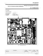
Page 8: ...R 2 8 R 6 7 C 5 4 R 3 24 C 1 20 R 4 0 C 3 67 R 6 3 C 55a R 3 8 U 1 0 2 D 2 2 Y 6 0 1 Q 5 R 5 5 R 1 2 6 U 4 R 61 R 1 4 0 S 1 C 3 7 2 C 3 3 C 3 7 1 J 1 1 5 J 1 0 4 C 3 4 J 1 0 3 L 8 L 7 J 1 1 2 J 1 1 3 J 1 1 4 R 2 5 R 1 9 R 3 0 2 X 2 R 1 2 4 X 3 R 125 R 127 R 118 Q 1 0 2 C 104 R 301 R 123 J 102 R 139 C 109 C 1 1 6 C 111 R 1 4 2 C 304 U 3 0 0 C 103 C 303 J 107 R 300 R 128 R 146 R 1 0 2 C 1 1 2 R 1 4 ...

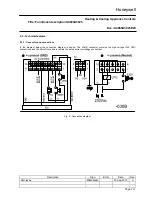
Page 9: ...e Rev First issue M Matiasko 01 Sep 2015 A Page 9 22 5 3 Technical features 5 3 1 Connector and connections In the diagram below the connection diagram is shown The Minifit connector contains the high voltage 230 VAC connections and the Microfit connectors contain the safety extra low voltage connections Fig 2 Connection diagram ...

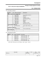
Page 10: ...Molex Minifit Neutral X1 8 Molex Minifit Neutral X1 9 Molex Minifit LPG output Neutral X1 10 Molex Minifit Main Power Line Neutral SPARK IGNITION CONNECTION TR1 2 8x0 5mm faston High voltage Transformer output FLAME INPUT CONNECTION X6 4 8x0 8mm faston Flame rod detection input EARTH CONNECTION 5 3 3 Communication Connector Connector name Pin Type of Connection Description X2 1 Molex Microfit Micr...

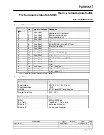
Page 11: ... X3 8 Molex Microfit NC X3 9 Molex Microfit NC X3 10 Molex Microfit GAS Reset from ELS in X3 11 Molex Microfit GND External Reset switch X3 12 Molex Microfit High Limit switch supply 24V X3 13 Molex Microfit NC X3 14 Molex Microfit GND X3 15 Molex Microfit GND X3 16 Molex Microfit GND from Esys 2 X3 17 Molex Microfit GND Heat Demand LV switch X3 18 Molex Microfit GND from ELS NOTE ELS External Loc...

Page 12: ...ength of wiring for external component 1 0 m max Ignition Value Spark voltage 20 kV Spark frequency 10 Hz Spark pulse energy 15 μAs Spark to ground Timings Value Pre purge waiting time 0 s Pre ignition time 0 4 s Safety time 10 s Number of ignition trials 3 Flame failure response time 1 s Stabilization time 0 s Post purge time 0 s adjustable Pump over run time Anti cycling time Flame sensing Value...

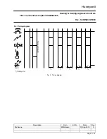
Page 13: ...Heating Cooling Appliance Controls Title Functional description S4965A3025 Doc S4965A3025E20 Description Sign E C N Date Rev First issue M Matiasko 01 Sep 2015 A Page 13 22 5 4 Timing diagram Fig 3 Timing diagram ...

Page 14: ...nuously the status of the switch and immediately activates the lockout state if the switch opens due to whatever reason A manual action is required to release the controller from the lockout state This can be done by the integral reset button or by the external communication 5 6 2 Alarm Error Led When an error condition is reached the Alarm Error LED indication output will be used to remote the fa...

Page 15: ...nd error conditions Several checks are included to protect the boiler and its environment Double High Limit sensor is constantly monitored safety times are constantly compared etc Any violation of programmable limits and or internal thermostat functions will lead to an error fault or warning condition Severe error igniter lockout will cause a lockout condition which can only be cleared by the rese...

Page 16: ...eral steps If check fails error 9 will be set FAULT 13 All remote resets communication are limited to 5 resets per 15 min If the limit is exceeded error will be generated and to reset it Power Off On and reset is necessary FAULT 21 ADC error FAULT 25 Matching error between Hup and Lup CRC codes different software versions FAULT 40 When Error input from Esys 2 signal is low This error condition is ...

Page 17: ...al description S4965A3025 Doc S4965A3025E20 Description Sign E C N Date Rev First issue M Matiasko 01 Sep 2015 A Page 17 22 7 Control Panel for ESYS A Control Panel for ESYS has been developed for monitoring In the following picture the default screen is shown ...

Page 18: ...o write some additional history information in non volatile memory 1 Error codes buffer of the 8 last errors Every error code has it s time information coupled with total hours 2 Total number of burner switching successfully finished burner sequence with flame on 3 Total number of lockouts 4 Number of burner on hours 5 Total number of hours with power supply on The history information can be acces...

Page 19: ... 01 Sep 2015 A Page 19 22 9 Other documentation This chapter contains references for further documentation of the ESYS and the CVI m valves which can be used in combination with the ESYS Title Reference Product Handbook ESYS EN2R9071 Product Handbook Modulating Valves EN2R9025 External Communication ERE2038 Terms used in Honeywell product handbooks EN2R9039 ...

Page 20: ... boiler control has a self check time of about 10 seconds NOTE 2 Electrical rating of connected controls should be appropriate for the load that is switched by the boiler control NOTE 3 Disconnect the boiler control from mains before performing a dielectric strength test NOTE 4 When first starting the control can be in the lockout condition reset the boiler control NOTE 5 The flame connection pin ...

Page 21: ...ended 3 mm 10 3 Cables and wirings Respect maximum connection cables length requirements Use connection cables with appropriate insulation working temperatures and moisture resistance Plan separate routes for cables that connect loads at low voltage SELV and loads at mains voltage HT Avoid connecting high and low voltage cables together The ignition cable must be laid so that it is separate from a...

Page 22: ...rrent is measured during 50 of the time the read out value is half of the real value The read out value has to be multiplied by 2 to get the real value If flame current is insufficient check that the flame sensing rod is fully enveloped by the flame and that the burner and the boiler control are reliable grounded Final checkout After installation and any adjustment start the appliance and observe ...

Reviews: