background image

EXCEL 10 FCU CONTROLLER LNS PLUG-INS USER GUIDE 

EN2B-0285GE51 R0909 

46 

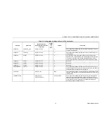
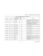
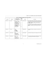
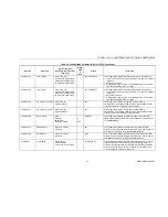
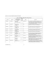
Table C2. Configuration Variables for Excel 10 FCU Controllers


NV name 

field name 

engineering units: 

English (metric) or states 

plus range 

digital 

state 

or 

value 

default comments


nciWallMod use_wall_mod_st_pt 

Bit 
NO 
YES 


YES 

This configuration variable specifies whether the setpoint used is from 
the knob on the wall module connected to the controller or from the 
network via nciTempSetPts. If set to NO, all setpoints to be used come 
from the network via nciTempSetPts. If set to YES, an additional option 
set_pnt_knob must be set to specify type of setpoint adjustment (see 
below). 

nciWallMod set_pnt_knob  2 

Bits 

OFFSET 
ABSOLUTE_MIDDLE 


OFFSET This 

configuration 

variable specifies specifies the usage of the setpoint 

knob on the wall module for the occupied setpoint. OFFSET specifies a 
relative scale on the wall module where the setpoint is calculated by 
adding the setpoint potentiometer value (± 5 K) to the appropriate 
value of nciTempSetPts. ABSOLUTE_MIDDLE specifies an absolute 
scale on the wall module. The setpoint knob directly determines the 
center point of occupied cooling and heating setpoints. The respective 
cooling and heating setpoint is determined by the setpoint knob 
position adding or subtracting half of the user selectable ZEB defined 
in nciSetPnts.<occ_mode>_cool or nciSetPnts.<occ_mode>_heat . 
This applies to <occ_mode> OCCUPIED and STANDBY. 

nciWallMod override_type  2 

Bits 

NO_BUTTON 
BYPASS_UNOCCUPIED 
BYPASS 


BYPASS_UNOCCUPIE

This configuration variable specifies the behavior of the override 
button. BYPASS_UNOCCUPIED allows overriding the current 
occupancy mode to OCCUPIED for a configurable bypass time, or 
causing a permanent override to UNOCCUPIED. BYPASS allows only 
the temporary override to OCCUPIED and canceling it. 

nciWallMod override_priority Bit 

LAST_WINS 
NETWORK_WINS 


LAST_WINS This 

configuration variable specifies the priority of the local (wall 

module push-button) or central (network interface) override. If 
NETWORK_WINS is set and the network sends value NUL, then the 
override button is active. 

nciWallMod display_type 

Bit 
LED_OVERRIDE 
LED_OCCUPANCY 
LCD_DISPLAY 


LED_OVERRIDE This 

configuration variable specifies the display of occupancy and/or 

override. LED_OVERRIDE shows the override from the bypass button 
or from the network. LED_OCCUPANCY shows the effective 
occupancy mode. LCD_DISPLAY is only used for T7560 Wall Modules. 
The display shows the occupancy mode with different symbols, and the 
override mode with flashing symbols. 


Summary of Contents for Excel 10 W7752D

Page 1: ...erformance Specifications 11 Configurations 12 General 12 Fan Type 12 Type of Heating and Cooling Equipment 13 Reheat Output 14 Digital Input 14 Excel 10 Wall Module Options 15 Abbreviations and Definitions 16 Application Steps 17 Overview 17 Step 1 Plan the System 17 Step 2 Determine Other Bus Devices Required 17 Step 3 Lay Out Communications and Power Wiring 18 LONWORKS Layout 18 Power Wiring 19...

Page 2: ...32 Appendix A Using An LNS tool to Commission a Fan Coil Unit 33 Temperature Sensor Calibration 33 Appendix B Configuring for Master Slave Operation 34 Output Configuration Options 34 Input Configuration Options 34 Equipment Control Options 34 Zone Control Options 34 Network Variable Binding 34 Appendix C LON Interface 35 Revision History page no change 13 Information on configuration of actuator ...

Page 3: ...nefits are achieved when the network communication capabilities are used A family of direct wired wall modules with a temperature sensor for space temperature measurement setpoint adjust ment bypass push button status LED and LCD display can be used in conjunction with Excel 10 FCU Controllers The wall modules are available in a variety of models incorporating various combinatinos of the following...

Page 4: ...tion Instructions 95 7554 Excel 10 FTT LPT 209541B Termination Module Installation Instructions Product Names The W7752 Controller is available in five models W7752D FCU Controller with 230 Vac power supply and with relay suitable for reheat applications W7752E FCU Controller with 230 Vac power supply without reheat relay W7752F FCU Controller with 115 Vac power supply with reheat relay suitable f...

Page 5: ...e fan coil units with optional electric heating coil The basic control sequence is shown in Fig 3 As space temperature falls below the heating setpoint the heating output is increased As space temperature increases above the cooling setpoint the cooling output is modulated to 100 Switching levels for staged heating cooling and fan speeds are configurable The fan may still be configured to run cont...

Page 6: ...d Setpoint Heating Occupied Setpoint 2 for Standby nvoActiveSetPt in cooling mode nvoSensor remote_set_point Cooling Standby Setpoint Heating Standby Setpoint 2 nvoActiveSetPt in heating mode nvoSensor remote_set_point Cooling Standby Setpoint Heating Standby Setpoint 2 When the Excel 10 FCU Controller is in the unoccupied mode the remote setpoint knob is ignored and the con figured setpoints for ...

Page 7: ...guration settings to the range of 12 30 C 2 Limited to the range of 10 35 C 3 setpoint knob ZEB 2 4 setpoint knob ZEB 2 Table 2 Example setpoint values based upon default configuration Relative setpoint knob C occupancy mode configured cooling setpoint configured heating setpoint ZEB setpoint knob 1 effective cooling setpoint 2 3 effective heating setpoint 2 4 occupied 23 21 2 2 21 19 standby 25 1...

Page 8: ...are two possible configurations having the following meanings LAST_WINS specifies that the last command received from either the wall module or nviManOccCmd determines the effective override state NETWORK_WINS specifies that regardless of the wall module override state the effective occupancy mode is determined by nviManOccCmd provided it has not been set to OC_NUL LED LCD LED Override The wall mo...

Page 9: ...ol Rec Ramp and Heat Rec Ramp which can be configured to cause the cooling and heating setpoints respectively to ramp up to their occupied settings from their unoccupied or standby settings prior to scheduled occupancy The Excel 10 FCU Controller uses the configured rates to determine the optimum time to start increasing the heating or cooling demand See the following figures The configuration par...

Page 10: ...peed up settling time Input NVs are received and output NVs are sent periodically This is the first mode after an application restart FLOATING OUTPUTS SYNCH The Excel 10 FCU Controller drives the floating control valves to their initial positions and then transitions to one of the control modes When the effective occupancy changes to unoccupied or standby after start up after 24 hours since the la...

Page 11: ...e Excel 10 W7754 FCU Controller is available in five basic models each with two different possibilities for LONWORKS transceivers Table 6 shows the differences between models Table 6 Excel 10 W7754 FCU Controller models OS number power input reheat relay W7754K1001 230 Vac W7754L1009 24 Vac W7754M1007 230 Vac W7754N1004 230 Vac W7754P1000 230 Vac X All wiring connections to the controllers are mad...

Page 12: ...ON UNUSED WALL MOD USED UNUSED DI2 USED 3 2 1 4 5 6 2324 7 8 GND 9 LED 10 FAN 11 DI2 12 DI1 SET SENS GND T7460 T7560 5 3 4 2 1 triac 0 5 A 2A M 2 A 10A 131415 18 17 16 III II I L N 230 V fan 19202122 close open close open com com 2526 L N 230 V D 71101 Schönaich Made in Germany 230 Vac 50 60 Hz max 5 VA unloaded W7754Kxxxx RS1A 23D25 OUT1 OUT2 230 Vac Fig 7 W7754 dimensions in mm ...

Page 13: ...n Coil Unit Controller version 2 0 Fig 8 shows the implementation used Hardware Output Fan Coil Unit Controller Object 8020 Mandatory Network Variables Manufacturer Defined Section Optional Network Variables Configuration Properties nv10 nviWaterTemp SNVT_temp_p nv9 nviSetPtOffset SNVT_temp_p nv8 nviApplicMode SNVT_hvac_mode nv7 nviOccCmd SNVT_occupancy nv6 nviFanSpeedCmd SNVT_switch nv16 nvoEffec...

Page 14: ...l Multi speed fans are switched at the same switching levels as multi staged heating control points see Fig 9 For example a three speed fan will switch ON its first speed at the same control level as the first stage of heating or cooling up until the second stage of heating or cooling where the second fan speed will switch on A two stage fan will switch with the first two stages of a 3 stage heati...

Page 15: ...ontrol will be returned to the normal control loop Valve action can be configured as either direct or reverse When in a two pipe system with a changeover input a floating actuator can be used which has the middle position 50 as the zero energy position The cool range is then 0 to 50 and the heat range 50 to 100 The output must be configured as floating mid Multi stage systems can be controlled wit...

Page 16: ...y mode will be occupied However if the TOD schedule indicates an occupied state and if the occupancy sensor contact is open then the effective occupancy mode will be standby The control algorithm will then control according to the standby setpoints configured for the heating and the cooling modes Configuring the digital input for movement or no movement dependent upon normally open or normally clo...

Page 17: ...ccupied for an indefinite time or it may be configured to only override to occupied The button may also be used to cancel the override Common Temperature Control Master Slave Controllers When one or more Excel 10 FCU Controllers serve a common area and a single temperature sensor is to be used a master slave arrangement can be configured One Excel 10 FCU Controller is configured for the local wall...

Page 18: ...nnected to a controller I x R I times R or current times resistance refers to Ohms Law V I x R K Kelvin LONWORKS Echelon LONWORKS network for communication among Excel 10 FCU Controllers NEC National Electrical Code the body of standards for safe field wiring practices NEMA National Electrical Manufacturers Association the standards developed by an organization of companies for safe field wiring p...

Page 19: ... between FCU Controllers on the LONWORKS network early in the job engineering process to ensure their implementation when configuring the controllers See section Step 6 Configure Controllers page 25 for information on the various Excel 10 FCU Controller parameters and on Excel 10 FCU Controller point mapping Step 2 Determine Other Bus Devices Required A max of 62 nodes can communicate on a single ...

Page 20: ... in Table 9 always apply Fig 13 and Fig 14 depict two typical daisy chain LONWORKS network layouts one as a single bus segment that has 60 nodes or less and one showing two segments Fig 15 shows examples of free topology bus layouts The bus configuration is set up using the Network Manager tool Excel 10 W7752 FCU Controller Excel 10 W7754 FCU Controller Excel 5000 Honeywell D 71101 Schönaich Made ...

Page 21: ...r of the LONWORKS wires is grounded Power Wiring IMPORTANT Notes on Power Wiring All field wiring must conform to local codes and ordinances See Table 10 for permitted wire sizes To minimize EMI noise do not run Triac and or relay output wires in the same conduit as the input wires or the LONWORKS communications loop To comply with CE requirements in the case of devices having a voltage range of 5...

Page 22: ...0 See Step 2 input wiring sensors contacts 14 to 20 AWG 2 0 to 0 5 mm2 multi conductor usually five wire cable bundle for runs 100 ft 30 m twisted pair or shielded cable is recommended 140 F 60 C rating Standard thermostat wire 82 5 ft 25 m output wiring actuators relays 14 to 20 AWG 2 0 to 0 5 mm2 20 AWG 0 5 mm2 acceptable for short runs any pair non shielded use heavier wire for longer runs NEC ...

Page 23: ...16 a common terminal for terminals 17 and 18 3 3 3 3 3 17 a triac output permanently configured to write output to OUT2 opening it 3 3 3 3 3 18 a triac output permanently configured to write output to OUT2 closing it 3 3 3 3 3 19 a common terminal for terminals 20 21 and 22 3 3 3 3 3 20 1 relay 1 permanently configured to write output to a three speed fan setting it to LOW 3 3 3 3 3 21 1 relay 2 p...

Page 24: ...3 3 3 3 3 16 2 relay 3 permanently configured to write output to a three speed fan setting it to HIGH 3 3 3 3 3 17 2 relay 2 permanently configured to write output to a three speed fan setting it to MEDIUM 3 3 3 3 3 18 2 relay 1 permanently configured to write output to a three speed fan setting it to LOW 3 3 3 3 3 19 a triac output permanently configured to write output to OUT1 closing it 3 20 a ...

Page 25: ...to for either a daisy chain or free topology LONWORKS layout See Fig 17 for connection details for a doubly terminated bus See Fig 18 for connection details for a singly terminated bus Two different LONWORKS termination modules are available LONWORKS termination module order no 209541B LONWORKS connection termination module mountable on DIN rails and in fuse boxes order no XAL Term 3 4 L O N Honey...

Page 26: ...RKS version w o releay for electrical reheat applications two triacs W7754P1000 230 Vac FTT LONWORKS version w releay for electrical reheat applications four triacs Excel 10 Wall Modules T7460 T7560 See Excel 10 wall module literature for details Excel 10 Sensors C7068A1007 Europe Air Temperature Sensor Return air Echelon Based Components and Parts 209541B FTT Termination Module Two required per L...

Page 27: ...med in a series of screens seen as file tabs under the menu option Application Selection and is easily followed using the tables included in this section There are 9 file tabs 1 Output 2 Input 3 Equipment Control 4 Fan 5 Switching Levels 6 Zone Options 7 Miscellaneous 8 PID 9 Wiring information only no configuring The specific parameters to be configured in each of these four categories are tabula...

Page 28: ...ut 1 triac 1 and 2 3 type floating floating mid2 1 stage 2 stage 3 stage PWM thermal floating floating PWM ther mal floating ther mal floating output 2 triac 3 and 4 3 control1 not used cooling heating heat cool changeover cooling cooling cooling output 2 triac 3 and 4 3 type floating floating mid2 1 stage 2 stage 3 stage PWM thermal floating floating thermal floating ther mal floating Notes 1 The...

Page 29: ...int pot limit for setpoint knob in either degrees F absolute setpoint 53 6 to 86 F or DDF relative setpoint 9 to 9 DDF limit for setpoint knob in either degrees C absolute setpoint 12 to 30 C or K relative setpoint 5 to 5 K 9 DDF 53 6 F for absolute setpoint 5 K 12 C for absolute setpoint max limit septoint pot limit for setpoint knob in either degrees F absolute setpoint 53 6 to 86 F or DDF relat...

Page 30: ...e 0 to 1200 seconds 150 s output 2 valve run time PWM period min stage ON time floating valve run time 20 to 600 seconds PWM cycle time 20 to 600 seconds 1 2 and 3 stage min ON time 0 to 1200 seconds 150 s reheat switching level 0 to 100 100 reheat hysteresis 0 to 100 5 PWM zero position 2 0 to 100 0 PWM full position 2 0 to 100 100 Notes 1 Valve action settings apply to floating PWM or thermal ty...

Page 31: ...tpoint 50 to 95 F 10 to 35 C 73 4 F 23 C heating occupied setpoint 50 to 95 F 10 to 35 C 69 8 F 21 C cooling standby setpoint 50 to 95 F 10 to 35 C 77 F 25 C heating standby setpoint 50 to 95 F 10 to 35 C 66 2 F 19 C cooling unoccupied setpoint 50 to 95 F 10 to 35 C 82 4 F 28 C heating unoccupied setpoint 50 to 95 F 10 to 35 C 60 8 F 16 C Notes 1 Ensure that unoccupied heating occupied heating occ...

Page 32: ...ing Troubleshooting Excel 10 FCU Controllers and Wall Modules In addition to the following information refer to the various Checkout and Test manuals for these products See Applicable Literature section for form numbers Alarms When an Excel 10 FCU Controller has an alarm condition it reports it to the central node on the LonWorks network via the variable nvoAlarm See Table 24 The information conta...

Page 33: ...ceTemp is bound and has failed in receiving an update within its specified FAILURE_DETECT_TIME ALM_COMFAIL_HVACMODE 9 nviApplicMode is bound and has failed in receiving an update within its specified FAILURE_DETECT_TIME ALM_COMFAIL_SETPTOFFS 10 nviSetPtOffset is bound and has failed in receiving an update within its specified FAILURE_DETECT_TIME ALM_COMFAIL_SCHEDOCC 11 nviTodEvent is bound and has...

Page 34: ...All other functions are normal in the SERVICE_MESSAGE mode If an FCU Controller does not have a bypass button connected it can still broadcast the Service Message on the network by temporarily shorting the controller Fan Speed Bypass input terminal to the AGND terminal on the controller terminals 5 and 7 with the controller in SERVICE_MESSAGE mode Manual Mode The FCU Controller can be put into a m...

Page 35: ...ool with the desired project loaded and the SLTA Q7752A connected to the LonWorks network perform the following procedure 1 Select a controller symbol from a network diagram 2 Click on Calibrate from the Controller menu Once the LNS tool logs on to the controller the Room Temperature Calibration dialog box appears 3 The box displays the Current Value of the sensor and the current Offset it also co...

Page 36: ... and no fan speed switch The digital input may be used on the slave units for window open closed or air flow fan fail detection and must be configured as such In the case of window sensing the window status network variable must be mapped to the master controller as the slave controller does not execute the control algorithm Equipment Control Options Valve action and fan interlock settings must be...

Page 37: ...LLER LNS PLUG INS USER GUIDE EN2B 0285GE51 R0909 35 APPENDIX C LON INTERFACE The tables are divided as follows Table C2 Configuration variables Table C3 Input variables Table C4 Output variables Table C5 Unused variables ...

Page 38: ......

Page 39: ...n the Intel Format and is four bytes in length nciApplVer time 1 UBYTE 0 to 255 0 See above nciApplVer time 2 UBYTE 0 to 255 0 See above nciApplVer time 3 UBYTE 0 to 255 0 See above nciDeviceName ch 0 17 UBYTE 0 to 255 0 This configuration variable specifies the name of each device This is an ASCII string with the a size of 18 characters A name with all NULLs means that the device has not been con...

Page 40: ... and nviApplicMode are not received at regular intervals that are less than the heartbeat time the controller will assume that there is a communication failure and revert to the occupied mode nciSndHrtBt SNVT_time_sec 0 to 6553 seconds 0 Disabled 0 s from factory This configuration variable specifies the maximum time that expires before the object automatically transmits the current value of nvoAc...

Page 41: ...vel to turn ON stage 2 of the cooling equipment if configured as multistage nciCntrlSettings switch_level_cool 2 SNVT_lev_percent 0 to 100 0 Disable 75 This is the switching level to turn ON stage 3 of the cooling equipment if configured as multistage nciCntrlSettings switch_level_heat 0 SNVT_lev_percent 0 to 100 0 Disable 5 This is the switching level to turn ON stage 1 of the heating equipment i...

Page 42: ...ft the temperature setpoint during demand limit control load shedding When nviDlcShed is different from zero the current occupancy setpoint will be decreased by this value for heating and increased for cooling nciEnergyManag si_optstart_grad 0 SNVT_temp_p 36 to 0 DDF hr 20 to 0 K hr 0 DDF hr 0 K hr This configuration variable specifies the cooling gradient used by the optimum start function to cal...

Page 43: ...dow switch contact DI_WINDOW_CLOSED normally open window switch contact DI_WINDOW_OPEN DI_MOVEMENT and DI_NO_MOVEMENT are supported starting with FCU2 version 1 0 3 These configuration settings cause the controller to retain the occupied state for 15 minutes after the last movement is detected nciFcuConfig fan_config BYTE NO_FAN ONE_SPEED TWO_SPEED THREE_SPEED 0 1 2 3 THREE_SPEED This configuratio...

Page 44: ... FLOATING ONE_STAGE TWO_STAGE THREE_STAGE PWM THERMAL FLOATING_MID 0 1 2 3 4 5 6 FLOATING This configuration variable specifies the output type to drive the connected actuator for the output 2 see above nciFcuConfig valve_reverse_0 Bit DIRECT REVERSE 0 1 DIRECT This configuration variable applies to only those outputs that have been configured as FLOATING PWM or THERMAL and specifies the direct re...

Page 45: ... the mini mum OFF time before switching to the next stage nciFcuConfig min_stage_off_time 1 SNVT_time_sec 0 to 600 seconds 90 s This configuration variable is used only for ONE_STAGE TWO_STAGE and THREE_STAGE output 2 and specifies the mini mum OFF time before switching to the next stage nciFcuConfig reheat_config BYTE REHEAT FREE_USE REL_NOT_USED 0 1 255 REHEAT This configuration variable specifi...

Page 46: ...Tv 1 SNVT_time_sec 10 to 3200 seconds 0 Disable 0 s This configuration variable specifies the derivative time for use in the derivative portion of the PID loop gain for the heating mode nciFcuGains si_boost 0 SNVT_temp_p 0 9 to 18 DDF 0 5 to 10 K 0 Disable 1 8 DDF 1 K This configuration variable specifies the temperature range to be added to the cooling setpoint above which the cooling output is f...

Page 47: ...cupied_heat SNVT_temp_p 50 to 95 F 10 to 35 C 60 8 F 16 C This is the configured setpoint which applies to the unoccupied heating mode nciWallMod ui_bypass_time UWORD 0 to 1080 minutes 180 min This configuration variable specifies the time the controller remains in OCCUPIED mode before reverting to the original occupancy mode after pressing the override button at the wall module or initiating BYPA...

Page 48: ...s The respective cooling and heating setpoint is determined by the setpoint knob position adding or subtracting half of the user selectable ZEB defined in nciSetPnts occ_mode _cool or nciSetPnts occ_mode _heat This applies to occ_mode OCCUPIED and STANDBY nciWallMod override_type 2 Bits NO_BUTTON BYPASS_UNOCCUPIED BYPASS 0 1 2 BYPASS_UNOCCUPIE D This configuration variable specifies the behavior o...

Page 49: ...ature control algorithm operates in a normal mode When it is 1 the effective setpoint will be shifted by the amount defined in nciEmergyManag si_dlc_setpt_bump For cooling the effective setpoint will be increased for heating the effective setpoint will be decreased always with regard to the frost protection limit nviEmerg SNVT_hvac_emerg EMERG_NORMAL EMERG_PRESSURIZE EMERG_DEPRESSURIZE EMERG_PURGE...

Page 50: ...rt This input variable is from an network connected operator inter face or other node that indicates the state of manual occupancy control schedule override It has priority over the time program nviTodEvent When the BYPASS mode is set the bypass time is active When the bypass time has elapsed the master controller automatically sets nviManOccCmd to OC_NUL nviManOccCmd does not provide a failure de...

Page 51: ...ding nvoStatus nviSensorOcc SNVT_occupancy OC_OCCUPIED OC_UNOCCUPIED OC_BYPASS OC_NUL 0 1 2 255 OC_NUL if bound but fails to be received or at application restart This input variable allows an occupancy sensor of another Excel 10 controller to be used to indicate the sensed occupancy state of the space OC_NUL means no input is available because it is not bound bound but not received periodically o...

Page 52: ... s temperature nviSpaceTemp may be set to a value other than INVALID using a LNS tool when nviSpaceTemp is not bound to set the temperature to a fixed value nviTest output1_cmd BYTE NORMAL_HC_MODE OFF1_OFF2 ON1_OFF2 OFF1_ON2 ON1_ON2 TESTPOSITION 0 1 2 3 4 5 NORMAL_HC_MODE at application restart This input variable is used by factory test OEM field test field installation and field testing to manua...

Page 53: ...OCCUPIED OC_UNOCCUPIED OC_STANDBY OC_NUL 0 1 3 255 OC_OCCUPIED if bound but fails to be received or at application restart This input variable indicates to the node whether the space is currently scheduled to be occupied standby or unoccupied nviTodEvent next_state SNVT_tod_event next_state OC_OCCUPIED OC_UNOCCUPIED OC_STANDBY OC_NUL 0 1 3 255 OC_OCCUPIED if bound but fails to be received or at ap...

Page 54: ... another controller to be used as remote window contact More than one nvoWindow may be bound to one nviWindow which allows one node to be used to handle several distributed window contacts In this case the control process assumes an open window if at least one bound window node detects an open window Window Closed would be assumed if all nvoWindows bound to nviWindow indicate the window being clos...

Page 55: ...TPTOFFS ALM_COMFAIL_SCHEDOCC ALM_COMFAIL_DLC ALM_COMFAIL_TEMPRESET ALM_COMFAIL_ODTEMP ALM_COMFAIL_OCCSENSOR ALM_COMFAIL_WINDOW ALM_COMFAIL_MANHEAT ALM_COMFAIL_MANCOOL ALM_HW_SW_MISMATCH RETURN_TO_NORMAL RTN_NODE_OFF RTN_FROST RTN_INVALID_SETPNT RTN_TEMP_SENSOR_FAIL RTN_SETPNT_KNOB_FAIL RTN_FAN_SPEED_SW_FAIL RTN_FAN_FAILURE RTN_COMFAIL_SPACETEMP RTN_COMFAIL_HVACMODE 0 1 2 3 4 5 6 7 8 9 10 11 12 13 ...

Page 56: ...me as nvoAlarm type See nvoAlarm type See above nvoAlarmLog alarm_type 3 Same as nvoAlarm type See nvoAlarm type See above nvoAlarmLog alarm_type 4 Same as nvoAlarm type See nvoAlarm type See above nvoAlarmLog alarm_type 4 is the oldest alarm nvoAlarmStatus error_bit 0 UBYTE Bit coded Alarm ALM_NODE_OFF ALM_FROST ALM_INVALID_SETPNT ALM_TEMP_SENSOR_FAIL ALM_SETPNT_KNOB_FAIL ALM_FAN_SPEED_SW_FAIL AL...

Page 57: ...perating as slave nvoCoolOutput will be transmitted immediately when its value has changed significantly 1 and periodically according to nciSndHrtBt The output value represents the output of the control algorithm but is limited to a range of 0 to 100 nvoDigitInState value SNVT_switch value 0 to 100 This output variable indicates the binary state of the controller s digital input which can be confi...

Page 58: ...OUTPUT_POS_1 FIELD_OUTPUT_POS_2 FIELD_REHEAT_RELAY FIELD_ACTIVE_SET_PT FIELD_SPACE_TEMP FIELD_REST_BYPASS_TIME 1 2 3 4 5 6 7 8 9 10 11 12 13 14 15 16 17 18 19 20 21 This output variable is used to indicate which other data field in nvoFcuStatus has changed since the last time nvoFcuStatus was sent out on the network If any field has had a significant change only that field is updated and field_no ...

Page 59: ...ancy sensor wired to the node nvoFcuStatus r_o_led SNVT_occupancy OC_OCCUPIED OC_UNOCCIPIED OC_BYPASS OC_STANDBY OC_NUL 0 1 2 3 255 This output variable reports the current state of the remote override LED which indicates the effective schedule override resulting from the bypass push button or a network override OC_OCCUPIED 2 flashes per second OC_UNOCCUPIED 1 flash per second OC_BYPASS on OC_STAN...

Page 60: ...the demand limit control nvoFcuStatus eff_window_open Bit CLOSED or NOT_ASSIGNED OPEN 0 1 This output variable indicates the real status of the window detection either from the digital input or from the network nvoFcuStatus hw_window_open Bit CLOSED or NOT_ASSIGNED OPEN 0 1 This output variable indicates the status of the digital input configured as a window contact nvoFcuStatus fan_feedback Bit F...

Page 61: ...s the current value in minutes of the active bypass timer nvoFcuStatusP field_no Same as nvoFcuStatus This output variable is the same as nvoFcuStatus except not sent as heartbeat This variable is sent only in response to a poll request typically from a supervisory device nvoFcuStatusP effect_occ Same as nvoFcuStatus Same as nvoFcuStatus nvoFcuStatusP hw_override Same as nvoFcuStatus Same as nvoFc...

Page 62: ...her Excel 10 controller operating as slave nvoHeatOutput will be transmitted immediately when its value has changed significantly 1 and periodically according to nciSndHrtBt The output value represents the output of the control algorithm but is limited to a range of 0 to 100 nvoReheat value SNVT_switch value 0 to 100 This output variable reports the actual state of the reheat output It can be boun...

Page 63: ...tory default configuration settings for the Fan Coil Unit controller Note that D and F versions and E G and J versions differ only in their supply voltage nvoSensorOcc SNVT_occupancy OC_OCCUPIED OC_UNOCCUPIED OC_NUL No Sensor 0 1 255 OC_NUL at application restart This output variable shows the state of the locally wired occupancy sensor if one is configured by nciFcuConfig DI1_config OC_NUL means ...

Page 64: ...able indicates whether an update nviRcvHrtBt is missing nvoStatus in_alarm Bit NO_ALARM IN_ALARM 0 1 This output variable indicates whether an alarm occured See nvoAlarm nvoStatus report_mask Bit NO_REPORT_MASK REPORT_MASK 0 1 This output variable shows the answer to nviRequest REPORT_MASK nvoTerminalLoad SNVT_lev_percent 163 163 163 835 INVALID This output variable shows the terminal load which i...

Page 65: ...ut variable reports the actual alarm status of the controller and is set to ALARM_NOTIFY_DISABLE when nviManualMode SUPPRESS_ALARMS nvoWindow value SNVT_switch value 0 to 100 0 at application restart This output variable reports the status of the window sensor It allows the locally wired window sensor to be used by other nodes on the network nvoWindow state SNVT_switch state CLOSED OPEN NO_WINDOW ...

Page 66: ...ects compatibility with other nodes or the equipment being controlled 3 The network interface or physical input output subsystem was revised and affects compatibility with other nodes NOTE Bug fixes may also be included in a minor functional release nroPgmVer bug_ver UBYTE 0 to 255 Bug Fix Number Network variables are unchanged A change to the algorithm network interface or physical input output s...

Page 67: ... as nvoFcuStatus Not used nvoFcuStatusP spare_field 0 Same as nvoFcuStatus Not used nvoSensor not_used 6 bits Reserved for future use nvoStatus out_of_limits Bit Not supported nvoStatus open_circuit Bit Not supported nvoStatus out_of_service Bit Not supported nvoStatus mechanical_fault Bit Not supported nvoStatus feedback_failure Bit Not supported nvoStatus over_range Bit Not supported nvoStatus u...

Page 68: ...on of Honeywell Technologies Sàrl Rolle Z A La Pièce 16 Switzerland by its Authorized Representative Automation and Control Solutions Honeywell GmbH Böblinger Strasse 17 71101 Schönaich Germany Phone 49 7031 63701 Fax 49 7031 637493 http ecc emea honeywell com Subject to change without notice Printed in Germany EN2B 0285GE51 R0909 ...

Reviews: