EXCEL 100C INSTALLATION INSTRUCTIONS
19
EN1R-0144GE51
R1007
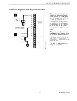
Terminal Assignment for Relay Modules
The relay modules facilitate the control of peripheral devices with high load via the
analog outputs of the controller.
The analog outputs provide an output current of 0 to 20 mA. Via an external 500-
Ω
resistor, an actuator with an input impedance of 500
Ω
can be used as 0 to 20 mA
device.
Specifications
•
Twelve outputs (AO1 to AO12)
0 to 10 Vdc (+10%) output
0 to 20 mA output current (via external 500-
Ω
resistor, see above)
0.1 mA max. sink output current
•
Protected inputs up to 24 Vac
•
8-bit resolution
•
±
100 mV/
±
1 LSB accuracy (1 LSB = 43 mV)
•
±
100 mV/
±
1 LSB zero point (1 LSB = 43 mV)
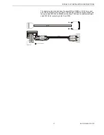
The relay modules are supplied via the
special relay connection of the controller
(terminals 65/66)
IMPORTANT
Important during connection:
1. Correct polarity
2. Under no circumstances may
a relay module be connected to
the reference voltage.
Several relay modules can be connected
in series via the bridged terminal pair:
Plus pole: Terminals 11/12 of the relay
Minus pole: Terminals 13 to 16 of the relay
MCD 3:
L
(Fig. left)
Terminal 17 controls the changeover
contact K3. Terminal 18 controls the ON
contacts K1, K2. Ground can be looped
through terminals 2/3.


