background image

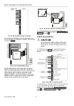
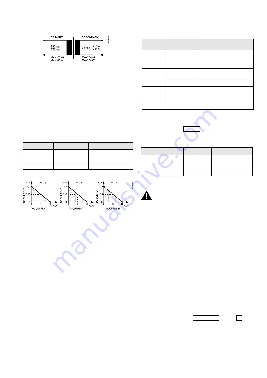
Fig. 69. Transformer example 

Use quick-acting backup fuse 10 A (or automatic H16 or L16) 
to protect transformer primary side. On the primary side of the 
CRT 2, there is a fusible output of type M 0.315 A (T) 250 V 
for the purpose of fine fusing. 

NOTE:


When selecting the appropriate transformer, con­
sider the number of Distributed I/O modules (see 
worst-case power consumption information below) to 
be used as well as the power requirements of all 
active sensors and actuators connected to the 
transformer. 

CRT-Series 

Table 12. Overview of CRT Series AC/DC current 

Transformer  max. AC current 

max. DC current 

CRT 2 

2 A 

0.5 A = 500 mA 

CRT 6 

6 A 

1.3 A = 1300 mA 

CRT 12 

12 A 

2.5 A = 2500 mA 

Fig. 70. AC/DC current graphs 

1450 Series 

All transformers of the 1450 series are designed for 50/60 Hz 
AC and have insulated accessory outputs. The transformers 
include built-in fuses, line transient/surge protection and AC 
convenience outlets and meet NEC class 2 requirements. 

EXCEL 500/600 INSTALLATION INSTRUCTIONS 

Table 13. 1450 Series transformers 

Part # 

1450 7287 

Primary side 

Secondary side 

-001 

120 Vac 

24 Vac, 50 VA 

-002 

120 Vac 

2 x 24 Vac, 40 VA and 100 VA 
from separate transformer 

-003 

120 Vac 

24 Vac, 100 VA and 24 Vdc 
600 mA 

-004 

240/220 Vac  24 Vac, 50 VA 

-005 

240/220 Vac 

2 x 24 Vac, 40 VA and 100 VA 
from separate transformer 

-006 

240/220 Vac 

24 Vac, 100 VA and 24 Vdc 
600 mA 

Standard Transformers 

Standard commercially available transformers must fulfill the 
specifications stated in Table 14. 

Table 14. Requirements for standard transformers 

Output voltage 

Impedance 

AC current 

24.5 Vac to 25.5 Vac 

 1.15 ohms 

max. 2 A 

24.5 Vac to 25.5 Vac 

 0.40 ohms 

max. 6 A 

24.5 Vac to 25.5 Vac 

 0.17 ohms 

max. 12 A 

Screw Terminal Block Installation Procedure

 WARNING 

High Voltage 

Risk of death or electrical shock. 
— Do not connect line power supply directly to the 

terminals. 

— Insulate devices with 120 Vac / 230 Vac by a 

transformer. 

1.


Make sure that the power supply of the cabinet is


disconnected.


2.


Make sure that the power supply of the cabinet is


disconnected and the communication module is


plugged in the housing.


IMPORTANT 

When installing a separate external transformer, do 
not connect the cabinet ground to the controller 
system ground. 

3.


If the distance between the controller and an actuator or 
sensor with 24 Vac supply is greater than 550 ft 
(170m): 

a)


Choose a transformer from the transformers 
listed in section "Power Supply" on page 32. 

b)  Connect the chosen transformer directly to the 

actuator or sensor. 

33


EN1R-1047GE51 R0902 

Summary of Contents for Excel 500

Page 1: ... XI582AH 12 Distributed I O Installation 13 Dimensions 14 Excel 500 600 14 Excel 500 XCL5010 15 XI582AH 16 Battery Activation during Commissioning XC6010 only 17 Replacing the Battery 17 Dismantling the Control Panel Unit 18 Dismantling the Control Panel Door Unit 18 Dismantling the Housing Cover 18 Dismantling the Excel 500 XCL5010 Control Panel Unit 18 Dismantling the XI582AH Operator Interface ...

Page 2: ...em Bus C Bus 37 Submodule Selection XC6010 37 System Bus Cable Specification 37 C Bus Extension by Using Repeaters 38 C Bus Termination Excel 600 38 C Bus Termination Excel 500 38 C Bus Termination Excel 500 XCL5010 38 Excel 600 Cable Specifications 39 Excel 500 Cable Specifications 40 Excel 500 XCL5010 Cable Specifications 41 MMI Cables 41 Modem or ISDN Terminal Adapter Connections 41 Changing Be...

Page 3: ...LONWORKS LonBuilder NodeBuilder LonManager LonTalk LonUsers LonPoint Neuron 3120 3150 the Echelon logo the LONMARK logo and the LonUsers logo are trademarks of Echelon Corporation registered in the United States and other countries LonLink LonResponse LonSupport and LonMaker are trademarks of Echelon Corporation 3 EN1R 1047GE51 R0902 ...

Page 4: ...ase refer instead to Distributed I O Product Data EN0B 0090GE51 21 Fig 44 has been changed 23 Fig 45 has been changed 27 The technical specifications of the XF521A analog input module have been expanded and Table 7 and Table 8 added 30 The technical specifications of the XF522A and XF527 analog output modules have been expanded 34 Section Pull Up Resistor Handling O S 2 04 00 or higher except for ...

Page 5: ...d Disconnect the power supply before you start to install mounted only by authorized and trained personnel the Excel 500 600 Controller Do not reconnect the power supply until you have completed installation If the unit is modified in any way except by the manufacturer all warranties concerning operation and safety are invalidated CAUTION Make sure that certain local standards and regulations Disc...

Page 6: ...he other Any combination is possible Fig 3 Up to five housings can be connected together When housings are alongside one another a minimum spacing of 1 5 in 35 mm should be taken into consideration to enable the hinged cover to be opened The maximum spacing between housings is limited by tailor made internal bus cables as shown in Fig 3 Excel 500 600 Internal Bus Wiring not XCL5010 Each housing ha...

Page 7: ...using location 1 AI XF521A XF526 any AO XF522A XF527 any DI XF523A any DO XF524A XF529 not in the 1 st housing 3 position output XF525A not in the 1 st module housing Coding the Terminal Block not XCL5010 The terminal block is coded with pins to prevent mixing the module types during commissioning or servicing Mixing the modules can damage them You can code the terminal block by inserting pins int...

Page 8: ...ule address can be seen on the label located next to the rotary HEX switch Fig 10 HEX switch label Care should be taken to ensure that each module gets its own module address Addressing the modules in ascending order 0 through F is recommended for the sake of clarity for maintenance personnel CAUTION Unplugging a module before switching OFF the power supply could destroy the module Do not unplug m...

Page 9: ...ssible at run time 6 Shift latches inwards until the housing is released 7 Set the module addresses see section Setting the Module Address not XCL5010 on page 8 8 Insert the modules Fig 14 Modules and ribbon cable 9 Plug the ribbon cable onto the computer module 10 Close the cover Extended wiring base wall mounting only US only As an alternative to the base plate an extended wiring base may be use...

Page 10: ...s plug in the communication module before connecting the power supply Always disconnect the power supply before unplugging the communication module Installation through a Control Panel Door not XCL5010 IMPORTANT Observer the minimum spacing of 1 5 in 35 mm when installing more than one housing Do not ex ceed the maximum spacing otherwise the tailor made internal bus cables will be too short 1 Prep...

Page 11: ...rminal block see page 7 6 Install the base Fig 21 Installing the wiring base 7 Complete electrical wiring 8 Lock the cover Fig 22 Locking the MMI cover Fig 23 Loosening the cover Fig 24 Removing cover 2 If mounting on a wall disconnect cable from panel for easier handling Fig 25 Disconnecting cable from cover 3 Route cable from the computer module XC6010 XC5010C XCL5010 11 EN1R 1047GE51 R0902 ...

Page 12: ... panel if removed in step 2 Fig 29 Making electrical connections 8 Reattach the cover Fig 30 Reattaching cover Deactivating Backlit Display of the XI582AH The XI582AH Operator Interface is equipped with an integrated backlit display to suit the display to the ambient lighting conditions By default this backlight is ON This can be disabled by means of a jumper if required The jumper is located at t...

Page 13: ... press of any of the eight operating keys If no entries are made for approximately two minutes the backlight turns itself off automatically until the next key is pressed again Fig 32 Backlight OFF jumper position When the jumper is disabled OFF position the backlight is permanently deactivated The contrast of the display can be adjusted using the potentiometer at the rear of the unit Fig 33 Contra...

Page 14: ...EXCEL 500 600 INSTALLATION INSTRUCTIONS Dimensions Excel 500 600 Fig 34 Excel 500 600 outside dimensions EN1R 1047GE51 R0902 14 ...

Page 15: ...EXCEL 500 600 INSTALLATION INSTRUCTIONS Excel 500 XCL5010 Fig 35 Excel 500 XCL5010 dimensions 15 EN1R 1047GE51 R0902 ...

Page 16: ...EXCEL 500 600 INSTALLATION INSTRUCTIONS XI582AH Fig 36 XI582AH dimensions EN1R 1047GE51 R0902 16 ...

Page 17: ... consumer return the waste batteries Dispose of the battery according to legal regulations During normal operation the battery is periodically tested under load If the battery voltage falls below a threshold of 2 45 V during operation or under load the computer module generates an error message which is displayed on the MMI as a system alarm The battery must be replaced as soon as possible after t...

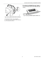
Page 18: ...efore dismantling the system disconnect the power supply To dismantle the control panel unit reverse the steps of the installation procedure see page 10 Dismantling the Housing Cover 1 Release the metal retaining clamp Fig 41 Housing cover retaining clamp 2 Pull off the cover Dismantling the Excel 500 XCL5010 Control Panel Unit Before dismantling the system disconnect the power supply e g by remov...

Page 19: ...to open the XI582AH Operator Interface 2 2 1 1 0000079b Fig 42 Removing Excel 500 XCL5010 from DIN rail 1 Dismantle the controller housing as depicted 2 Pull the lower part of the housing off the control panel 3 Lift the housing from DIN rail Fig 43 Opening the XI582AH Operator Interface unit 19 EN1R 1047GE51 R0902 ...

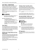
Page 20: ...t necessary if the general guidelines for cable routing are observed If in certain cases the routing guidelines cannot be observed then shielded cable must be used The shield must not be terminated at a controller instead to avoid ground loops the shield must be grounded at only one end at the control panel To prevent ground loops shielding of input output cables leading to peripheral devices must...

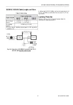
Page 21: ...er supply 16 AWG 1 5 mm 2 14 AWG 2 5 mm 2 Low voltage signals 1 20 AWG 0 5 mm 2 1 0 to 10V sensors totalizers digital inputs 0 to 10V signals for actuators etc Lightning Protection Please contact your local Honeywell representative for information on lightning protection MAX 1300ft 400m EXTERNAL TRANSFORMER MIN 20AWG 0 5mm2 24Vac 230Vac 120Vac PRIMARY VOLTAGE TRANSFORMER PRIMARY VOLTAGE Y 24 Vac 2...

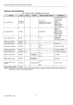
Page 22: ...dule XP502 1 0 1 x Power supply Watchdog ext battery operation Analog input module XF521A 8 Analog input module XF526 8 CPU active Analog output module XF522A 8 0 5 x 1 Auto 8 x Output intensity Analog output module XF527 8 8 x Output intensity Digital input module XF523A 12 12 x Status invertible Digital output module XF524A 5 changeover 1 NO contact 0 5 x 1 Auto 6 x Status Digital output module ...

Page 23: ...ker The primary coil of the CRT 6 contains a 0 8 A 250 V quick blow fuse Table 5 gives an overview of the transformers of the 1450 series U S Table 5 1450 series transformers data Part 1450 7287 Primary side Secondary side 001 120 Vac 24 Vac 50 VA 002 120 Vac 2 x 24 Vac 40 VA and 100 VA from separate transformer 003 120 Vac 24 Vac 100 VA and 24 Vdc 600 mA 004 240 220 Vac 24 Vac 50 VA 005 240 220 V...

Page 24: ...hen connecting a modem or when monitoring via a central XD505A or XD508 can be used for local bus communication XDM506 is used for modem communication A stand alone controller can be operated without a submodule XC5010C Computer Module CAUTION Do not unplug the computer module with the power still connected since this could destroy the module First switch S1 on the power supply module to the 0 pos...

Page 25: ...or Interface or the Xl584 Operator and Service Computer to be connected As an option the XI582AH can be connected at the rear of the com puter module XC5010C When connecting to the back of the module the switch on the front panel of the XC5010C must be set to Rear XP502 Power Supply Module Fig 53 shows the pin out of the XP502 Power Supply module Fig 53 XP502 Power supply module and watchdog circu...

Page 26: ... No other devices may be connected to the XAPU 24 2F Fig 55 Connection of XAPU 24 2F UPS Distributed I O modules NOTE There must be no connection between GND of the XC5010C CPU module and the GND of Distributed I O modules Relay K1 insures that the supply of the Distributed I O modules will be switched OFF by switching OFF the XP502 Power Supply module The power consumption of the Excel 500 contro...

Page 27: ...d OFF XF521A Analog Input Module Technical Specifications Number eight inputs AI1 AI8 Input 0 10 Vdc low input impedance 25kOhm to 10 V 200kOhm to GND 0 20 mA via external 500 ohm resistor 4 20 mA via external 500 ohm resistor NTC 20K ohm 50 150 C PT1000 50 150 C Protection up to 40 Vdc 24 Vac Resolution 12 bit resolution Accuracy 75 mV or 0 75 0 10 V Table 7 Accuracy of analog input sensors Measu...

Page 28: ...or NTC 20K ohm 50 150 C PT1000 50 150 C PT1000 0 400 C PT100 50 150 C PT3000 50 150 C Balco 500 50 150 C Protection up to 40 Vdc 24 Vac Resolution 12 bit resolution Accuracy 75 mV or 0 75 0 10 V Table 8 Accuracy of analog input sensors Range Measurement error without sensor tolerance PT1000 NTC 20K 58 4 F 50 20 C 1 2 K 5 0 K 4 32 F 20 0 C 0 7 K 1 0 K 32 86 F 0 30 C 0 5 K 0 3 K 86 158 F 30 70 C 0 7...

Page 29: ...ergized normally open contacts In the OFF position the LED will illuminate when de energized normally closed contacts Max signal voltage from non Honeywell voltage sources DC Voltage Vmax 40 V AC Voltage Vmax 28 V 50 Hz Input resistance Ri 15k ohms Fig 62 XF523A connection examples If the inputs are used as totalizers Table 9 applies Table 9 Totalizer inputs specifications Input Frequency Pulse du...

Page 30: ...l Output Modules Technical Specifications Number 6 digital outputs Voltage rating 240 Vac max per contact and per module Current rating 4 A max per contact 12A max per module Relay contacts K1 to K5 changeover contact voltage free K6 normally open contact voltage free Fig 64 XF524A and XF529 Digital Output module NOTE Maximum voltage for U S is 24 V NOTE Both modules are fully pin compatible Begin...

Page 31: ...16 miniature circuit breaker or G 10 A quick blow fuse should be used to protect the 240 Vac mains supply Voltage rating 240 Vac or 28 Vdc max NOTE The maximum voltage for the U S is 24 V Current rating 0 2A max at 240 Vac 1 2A max at 28 Vdc Fig 65 XF525A Three position output module 31 EN1R 1047GE51 R0902 ...

Page 32: ... 9 6 Kbaud Table 11 Signals of serial port Signal type Controller output Controller input Signal ground Transmit x Receive x Carrier detect x Clear to send x Data terminal ready x 5 V x MMI Connection For direct communication the external operator interface XI582 and the PC based MMI XI584 can be connected to the serial port Power Supply The Excel 500 XCL5010 controller is powered by an external t...

Page 33: ... transformer 003 120 Vac 24 Vac 100 VA and 24 Vdc 600 mA 004 240 220 Vac 24 Vac 50 VA 005 240 220 Vac 2 x 24 Vac 40 VA and 100 VA from separate transformer 006 240 220 Vac 24 Vac 100 VA and 24 Vdc 600 mA Standard Transformers Standard commercially available transformers must fulfill the specifications stated in Table 14 Table 14 Requirements for standard transformers Output voltage Impedance AC cu...

Page 34: ...nal 2 on Screw Terminal Block Fig 72 Connecting to a screw terminal IMPORTANT If there already are additional transformers for example supplying actuators or active sensors connect the 24 Vac secondary side of the transformers together 8 Attach the terminal blocks to the housing as shown in Fig 73 Fig 73 Attaching screw terminal block Pull Up Resistor Handling O S 2 04 00 or higher except for XFL5...

Page 35: ...l Inputs O S 2 04 00 or higher When the input is identified as a DI point in CARE DI subtype AI the internal pull up resistor is disabled 10 Vdc Range Measurement error without sensor tolerance Pt1000 NTC 20k ohms 58 to 4 F 50 to 20 C 1 2 K 5 0 K 4 to 32 F 20 to 0 C 0 7 K 1 0 K 32 to 86 F 0 to 30 C 0 5 K 0 3 K 86 to 158 F 30 to 70 C 0 7 K 0 5 K 158 to 212 F 70 to 100 C 1 2 K 1 0 K 212 to 266 F 100...

Page 36: ...tion for that cable type and bus type for each repeater used For example adding repeaters for a doubly terminated bus using JY St Y 2x2x0 8 cable increases the maximum length 3000 ft 900 m for each repeater On the Excel 500 XCL5010 controller the LONWORKS bus connections are located on the communication module as shown in Fig 78 LON SERVICE BUTTON POWER GRN LON SERVICE RED LEDs C BUS TxD YEL C BUS...

Page 37: ... baud 76800 baud If the system bus speed throughout the system life time is restricted to 9600 baud then a submodule XD505A should be chosen Otherwise the XD508 must be used NOTE All communication submodules on one bus must be of the same type i e either uniquely XD505A or uniquely XD508 Do not use a mix between submodules XD505A and XD508 on the same bus IMPORTANT For communication with more than...

Page 38: ...0 Order no for repeaters Description US order No European order no without housing 14507324 001 with housing 14507324 002 XD509 C Bus Termination Excel 600 The XC6010 CPU module may have either the XD505A or the XD508 submodules mounted on them for C Bus communication Table 18 provides baud rate information for selecting the module The XD508 submodule is equipped with a DIP switch which activates ...

Page 39: ...E Modules listed in Compatibility column are used in Excel 20 100B 500 600 Controllers Excel 600 Cable Specifications For connection to the XI582 Operator Interface two tailor made cables are available XW564 cable length 7 ft 2 5 m XW565 cable length 15 ft 5 m EXCEL 500 600 INSTALLATION INSTRUCTIONS For connection to the XI584 Operator and Service Computer a tailor made cable is available with plu...

Page 40: ...ected to the front of the XC5010C computer module with the following cable XW585 cable length 15 ft 5 m Fig 88 Excel 500 XI584 operator and service computer cable details NOTE You can also use a standard null modem cable An adapter cable is needed when the same MMI unit XI582AH or XI584 is used on a site where there is a mix of XC5010C and XC6010 CPU modules Always use the new cables XW582 and XW5...

Page 41: ...I cable details EXCEL 500 600 INSTALLATION INSTRUCTIONS Modem or ISDN Terminal Adapter Connections For remote communications a modem or ISDN terminal adapter can be connected directly to the serial port of the Excel 500 XCL5010 Controller The serial port of the Excel 500 XCL5010 controller accepts a standard modem cable with a female 9 pin connector Use the cable that is supplied with the modem IS...

Page 42: ...EXCEL 500 600 INSTALLATION INSTRUCTIONS Fig 90 Excel 500 and Excel 600 used together with XI584 and XI582 Operator Interfaces Fig 91 XW584 cable details EN1R 1047GE51 RR0902 42 ...

Page 43: ...able with a female 9 pin connector Fig 93 Serial port location on Excel 500 XCL5010 Use the cable that is supplied with the modem ISDN terminal adapter The communication speed is 9600 baud by default but can be set as high as 38 4 Kbaud NOTE See section Serial Port on page 32 for signals of serial port Modem Requirements Modem must support Hayes compatible command set not V150 or V151 Microsoft co...

Page 44: ...he modem to consider 1 Do not wait for the public network dial tone Typically the init command ATX3 will trigger the modem to dial without waiting for a public network dial tone Save this modem set up in the modem EEPROM with the command AT W Check the modem handbook to verify the correct commands Note that these commands are executed automatically with the RESET MODEM command 2 Add the prefix req...

Page 45: ...rning devices which causes the vehicle s horn to sound or the lights to flash Drivers are advised not to use the handheld microphone or the telephone handset while their vehicle is in motion except in emergencies Use the hands free facility to speak only if it does not divert your attention from the traffic Operation of the M20T can disrupt the operability of inadequately protected medical devices...

Page 46: ...915 MHz Frequency RX 935 960 MHz Impedance 50 ohms VSWR TX max 1 7 1 installed VSWR RX max 1 9 1 installed Gain 1 5 dB referenced to λ 2 dipole 3dB width of cone vertical 80 horizontal 360 Max power 1 W cw 2 W peak at ambient temperature of 55 C Depending on the application and the RF field at the local site the GSM antenna may be mounted directly or via cable The maximum antenna cable length is 8...

Page 47: ...g of the MMI of the CPU is disturbed or that the outputs behave abnormally M20 Terminal Set up Prior to beginning the set up get the M20T manual or CD ROM if it was delivered with one Everything is described in it and you will need it IMPORTANT It is absolutely mandatory to use a serial data line monitor for the set up of the M20T Without such a device being connected between the serial port of th...

Page 48: ... steps 1 Connect the XI582AH MMI 2 Enter PIN 3 Disconnect the XI582AH MMI 4 Connect the M20T 5 Reconnect the XI582AH MMI 6 View the PIN field 7 If it shows 0 the PIN was wrong 8 If it shows PIN the PIN was correct Additional information about the M20 terminal may be found at the following website http www siemens de ic products cd english index products cellular m20t html Control Products Control ...

Reviews: