DISTRIBUTED I/O
21
EN0B-0090GE51 R0802
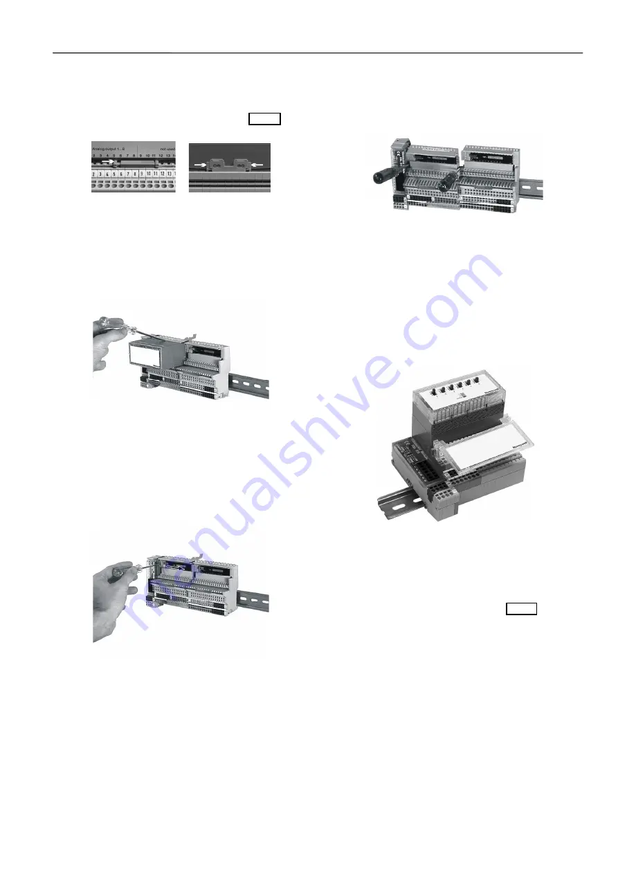
Removing Modules and Terminal Blocks
The electronics modules and terminal blocks can be removed
by carrying out the following steps:
1.
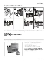
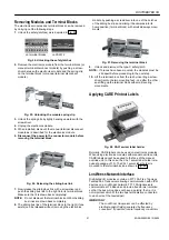
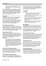
Unlock the safety latch(es) as is depicted in Fig. 24.
on terminal blocks on XSL512
Fig. 24. Unlocking the safety latches
2.
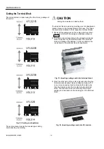
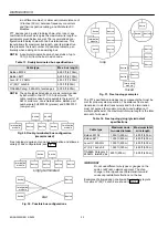
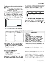
Remove the electronics module from the terminal block (or
manual terminal disconnect module) by pushing a screw-
driver between the electronics module and the spring clip
on the terminal block (or manual terminal disconnect
module).
Fig. 25. Unlocking the module spring clip
3.
Unlock the spring clip by lightly bending upwards with the
screwdriver.
4.
Unplug the electronics module.
5.
When installed, dismount the manual terminal disconnect
module as is described for the electronics module.
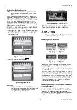
6. Disconnect the power to the connector module before
removing the terminal block.
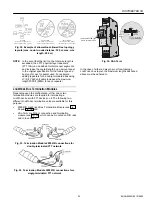
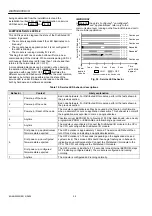
Fig. 26. Releasing the sliding bus link
7.
Now release the sliding bus link with a screwdriver and
push the sliding bus link to the right into its terminal block.
Make sure that it is drawn back completely!
NOTE:
Do not dismount the terminal block until both sliding
bus links are drawn back completely.
8.
The sliding bus link of the terminal block to the right (if one
exists) can be released without removing the electronics
module by pushing a screwdriver into one of the notches
of the sliding bus link and sliding it backwards into its
home position (terminal block) with small sideways move-
ments.
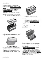
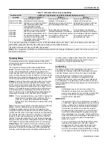
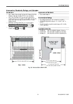
Fig. 27. Removing the terminal block
9.
Unlock and dismount
the type-C safety latch.
NOTE:
If braces have been mounted, the modules must be
slid apart before proceeding to the next step.
10.
Lift
the terminal block from the rail by inserting a screw-
driver tip into the two mounting feet - one after the other -
and lifting up the terminal block with small levering
movements.
Applying CARE Printout Labels
Fig. 28. XAL1 swivel label holder
Normally, CARE labels can be used on electronics modules.
When using electronics modules with manual override units,
CARE labels cannot be applied to the face of the manual
override unit. In this case, the XAL1 swivel label holder is re-
quired (package of 10). The XAL1 swivel label holder is
mounted to the terminal block as shown in Fig. 28.
L
ON
W
ORKS
Network Interface
Distributed I/O modules contain an FTT-10A Free Topology
Twisted Pair Transceiver allowing communication with other
devices on a L
ON
W
ORKS
network. FTT-10A transceivers
communicate at 78 Kbaud and provide transformer isolation
so that the bus wiring does not have a polarity; that is, it is
not important which of the two bus terminals are connected
to each wire of the twisted pair.
IMPORTANT
The L
ON
W
ORKS
transceiver can be affected by
electromagnetic fields generated by frequency
converters. If possible, locate frequency converters


