background image

DISTRIBUTED I/O

EN0B-0090GE51 R0802

6

Analog Output Module XFL522B

  Eight outputs (AO1 – AO8), short-circuit proof

  Signal levels 0...10 Vdc

U

max

 = 11 Vdc, I

max

 = +1 mA, -1 mA

  Protected outputs up to 40 Vdc / 24 Vac

 8-bit 

resolution

  Zero point < 200 mV

  Accuracy ± 150 mV deviation from output voltage

  One red LED per channel (light intensity proportional to

output voltage)

  Green power LED (L1) and red L

ON

W

ORKS

 status LED

(L2)

  Control updating every 1 sec with CPU

  Dimensions (WxLxH): 47x97x70 mm

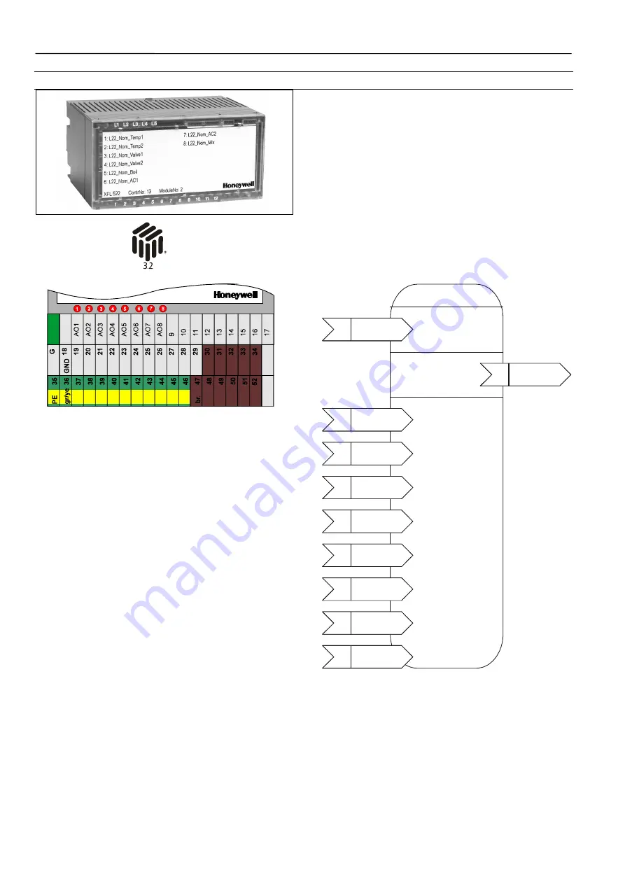
This analog output module has eight output channels

which can be connected to actuators or other suitable

analog devices.
The unit plugs into the XSL513 Terminal Block and can be

inserted and removed without disturbing other units on the

bus. Terminals AO1 through AO8 are the analog outputs.

Terminals 9 through 17 are connected to ground. Eight red

LEDs are located on top of the module. The brightness of

each LED is proportional to the output level of the cor-

responding channel. The module address is set using the

rotary HEX switch (in the case of applications prior to

CARE 4.0).

Open Loop Actuator

Object Type #3

Mandatory

Network

Variables

input

NV 1

nviRequest

SNVT_obj_request

nv1

nviValue

SNVT_switch

input
NV 1

nviRequest

SNVT_obj_request

nv3

nvoFeedback

SNVT_switch

Optional

Network

Variables

Optional

Configuration

Properties

input

NV 1

nviRequest

SNVT_obj_request

nc1

UCPTSensorConfig

input

NV 1

nviRequest

SNVT_obj_request

nc2

UCPTdriveTimeClose

input

NV 1

nviRequest

SNVT_obj_request

nc3

UCPTdriveTimeOpen

input
NV 1

nviRequest

SNVT_obj_request

nc4

UCPTsyncMin

input
NV 1

nviRequest

SNVT_obj_request

nc5

UCPTsyncMax

input
NV 1

nviRequest

SNVT_obj_request

nc6

UCPTsyncCharge

input
NV 1

nviRequest

SNVT_obj_request

nc88

UCPTminDeltaLevel

input

NV 1

nviRequest

SNVT_obj_request

nc96

UCPTdelayTime

Fig. 3. L

ON

M

ARK

 Object for each analog output

Summary of Contents for Excel 5000 open XFL521B

Page 1: ...e terminal block allowing communication with controllers via the built in Echelon LONWORKS bus interface The ter minal block provides spring clamp terminals for easy connec tion of field cables from the various sensors and actuators The modular system allows Distributed I O modules to be removed from the system without disturbing other modules The module with terminal block mounts easily onto a DI...

Page 2: ...updating of all output NVs and handling of input NVs Setting the Node Object to ENABLE via nviRequest returns the module to normal operation The Node Object also contains the optional NV nciNetConfig which is initialized to CFG_LOCAL by default This allows the Distributed I O module to set its location string If a network management node commands this nci to CFG_EXTERNAL then the module will no lo...

Page 3: ...ation parameter files accessed by network management read write messages SCPTMinSendTime SNVT_time_sec 1 0 to 10 0 sec default 1 0 sec Defines the minimum period of time between output variable transitions This configuration property is applicable only to output NVs of the input modules SCPTMaxSendTime SNVT_time_sec 1 0 to 6553 4 sec default 60 0 sec Defines the maximum time period of time before ...

Page 4: ...og inputs and terminals 9 through 17 are wired together and provide an auxiliary voltage of 10 Vdc The module address is set using the rotary HEX switch in the case of applications prior to CARE 4 0 NOTE In the case of applications prior to CARE 4 0 when the input is configured as a slow DI the internal pull up resistor is disabled Open Loop Sensor Object Type 1 Mandatory Network Variables input N...

Page 5: ...ected to either an NTC20k or PT1000 sensor with a resolution of 0 1 C If the sensor channel is configured as a voltage input the temperature value is invalid 0x7FFF UCPTSensorConfig 0 not used 9 0 to 10V with pull up resistor 4 NTC20 5 PT1000 10 0 to 10V without pull up resistor default 8 Specifies the type of sensor for a particular input channel UPCTSendOnDelta SNVT_count 0 to 4095 default 2 Spe...

Page 6: ...ght red LEDs are located on top of the module The brightness of each LED is proportional to the output level of the cor responding channel The module address is set using the rotary HEX switch in the case of applications prior to CARE 4 0 Open Loop Actuator Object Type 3 Mandatory Network Variables input NV 1 nviRequest SNVT_obj_request nv1 nviValue SNVT_switch input NV 1 nviRequest SNVT_obj_reque...

Page 7: ... SCPTdelayTime SNVT_time_sec 0 0 to 10 0 sec default 5 0 sec Specifies the delay time before a floating actuator changes its direction This avoids mechanical problems that could occur when the run direction changes due to an update to nviValue while the actuator is still moving SCPTminDeltaLevel SNVT_lev_cont Specifies the delta level for an update to nviValue to be exceeded before a new position ...

Page 8: ...ontrols the changeover contact K1 Power Supply Several relay modules can be connected in series via the bridged terminal pair 24 Vac Terminals 11 12 of the relay 24 Vac Terminals 13 to 16 of the relay MCD3 24 Vac Terminals 13 to 15 of the relay MCE3 Attention Always connect the same side of the transformer to the same side of XSL511 24 Vac 20 230 Vac 120 Vac fuse dependent upon your transformer fu...

Page 9: ...auxiliary voltage of 18 Vdc The module address is set using the rotary HEX switch in the case of applications prior to CARE 4 0 Beginning with Excel 500 controller firmware version 2 04 00 the online point attribute Normally Open Normally Closed NO NC defines the relation between the physical state contact position and its logical status See Table 7 Open Loop Sensor Object Type 1 Mandatory Network...

Page 10: ...to 65534 65534 initial value Transmits the state of the input channel every time there is a state change or if SCPTMaxSendTime in the Node Object is expired If configured as a totalizer this NV transmits the number of transitions from 0 to 1 UCPTSensorConfig 0 not used 1 binary default 2 totalizer Specifies the setting for a sensor channel UCPTSendOnDelta SNVT_count 0 to 65535 Specifies the differ...

Page 11: ...ally Closed NO NC defines the relation between the physical state relay on off and its logical status See Table 9 NOTE The relays can be used to switch signals with up to 230 Vac and 2 A All outputs from a single module must be of the same kind It is not allowed to mix high voltage e g 230 Vac and low voltage e g 24 Vac signals Table 9 Physical state and logical status as defined by the point attr...

Page 12: ...d and the value field will contain the actuator position If the manual override switch is in the automatic posi tion data is transmitted whenever nviValue is written If the manual override switch is in the manual position data is transmitted whenever the manual position is changed nvoManCnt SNVT_count 0 to 65535 Transmits the number of manual switching operations Each transition from the auto manu...

Page 13: ... yellow connected together to the DIN rail Six interconnected auxiliary terminals brown NOTE Both rows of brown terminals are connected internally but are not connected to the electronic module Terminal Block XSL514 for XFL524B Mounts on a DIN rail top hat rail Spring clamp terminals Safety latch secures XFL module in its position Mechanical coding using coding pins an optional package with 20 cod...

Page 14: ... including point name status manual auto and point value provided to CPU The XFR524A manual override module mounts directly on top of the XFL524B Six switches on top of the module can be used to independently switch each of the digital outputs OFF 0 or ON 1 Each switch also has an automatic setting which causes the channel to operate normally The LEDs of the XFL524B are also visible The manual ove...

Page 15: ...L511 RXE090 1 07 A 0 9 A 0 73 A 0 65 A 0 57 A 0 49 A XSL511 RXE160 1 9 A 1 6 A 1 3 A 1 15 A 1 01 A 0 86 A Calculate the worst case current draw for the Distributed I O modules and the Excel 500 XCL5010 controller to be connected to the transformer based on the input voltage stated in Table 12 Table 12 Max current ratings for other modules Maximum current rating at Module 19 2 Vac 28 8 Vac 19 2 Vdc...

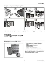
Page 16: ...e terminal block if the sliding bus connector is not on the left side 9 Fit the end cover included with the XSL511 onto the last module 10 Install 3 rd party DIN rail end bracket close to end cover of the last module NOTE It is recommended that you use solid standard 3 rd party DIN rail end brackets on both ends of the terminal block to prevent any movement of the terminal blocks Terminal blocks m...

Page 17: ...age 29 for additional parts which may be needed for mounting Manual Terminal Disconnect Module XSL512 Mounts between terminal blocks and Distributed I O modules Manual terminal disconnect switches 18 disconnect switches Dimensions WxLxH 58x97x55 mm Safety latch secures XFL module in its position The XSL512 Manual Terminal Disconnect module allows each of the terminal block s input connections to b...

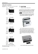
Page 18: ...at the comb is left with the coding combinations shown in Fig 12 2 The comb side corresponding to the respective terminal block is inserted into the location holes in the terminal block and broken off positions 1 to 9 are printed on the circuit board of the terminal block for alignment Fig 13 Inserting coding comb into terminal block 3 Next the other side of the comb is inserted into the elec tron...

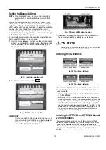
Page 19: ...t strip cable Fig 17 Rotary HEX switch location 3 The module address is set by turning the HEX switch to the appropriate address code using a screwdriver CAUTION Do not plug an XFL module without a cover or manual override module into the terminal block Installing the I O Modules locking procedure locked latch Fig 18 Type A safety latch locking procedure locked latch Fig 19 Type B safety latch The...

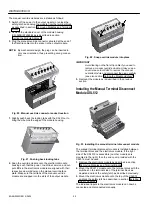
Page 20: ...l override module are snapped into the slots of the output module Fig 22 Snap override module into place IMPORTANT Avoid tearing on the flat strip cable if you need to remove a manual override module Always use a cover release tool XAL2 to remove the manual override module and disconnect the plug carefully see also section Setting the Module Address 3 Remount the module as is described in the prev...

Page 21: ... pushing a screwdriver into one of the notches of the sliding bus link and sliding it backwards into its home position terminal block with small sideways move ments Fig 27 Removing the terminal block 9 Unlock and dismount the type C safety latch NOTE If braces have been mounted the modules must be slid apart before proceeding to the next step 10 Lift the terminal block from the rail by inserting a...

Page 22: ... bus configuration recommended Free topology requires only one bus termination and allows a variety of bus configurations see Fig 30 termination module device device device device device device singly terminated device device device device star termination module Fig 30 Possible bus configurations device device device device device termination module termination module device device device device ...

Page 23: ...ype for each repeater used For example adding repeaters for a doubly terminated bus using JY St Y 2x2x0 8 cable increases the maximum length 3000 ft 900m for each repeater LONWORKS Bus Termination Modules Depending upon the configuration either one or two termination modules are required for terminating a LONWORKS bus with FTT devices on it The following two different LONWORKS termination units ar...

Page 24: ...er type Controller firmware Open LONWORKS functionality XFL52x XFL52xB CARE 4 0 LONWORKS binding LM4W binding 2 00 xx 2 03 xx not possible local local not possible not possible 2 04 xx not possible local local shared not possible not possible XC5010C XCL5010 2 06 xx not possible local local shared not possible not possible XD50 FL XD50 FCL 2 04 xx 2 06 xx not possible not possible not possible not...

Page 25: ... the host Excel 500 controller NOTE It is recommended that you use CARE to assign the Distributed I O modules to the host Excel 500 con troller i e to enter the Distributed I O modules Neuron IDs The alternative is to assign them using the MMI Open The term open refers to an interoperable LONWORKS system in which CARE has been used to generate a LONMARK compliant network interface file capable of ...

Page 26: ...uron ID entered via the MMI the assignment carried out via the MMI will have priority Flashing of Distributed I O Module Assignment The Distributed I O module assignment that was made in CARE or via the controller MMI must be manually saved to Flash memory When Distributed I O module assignment has been made during the test mode the assignments are automatically saved in Flash memory These assignm...

Page 27: ...ble causes no no Power OFF CPU not working Incorrect wiring Sliding bus connector on XSL511 not closed properly Defective hardware contact your Honeywell dealer yes no Sliding bus connector on the left side not closed properly Defective hardware contact your Honeywell dealer yes yes Wrong LONWORKS address HEX switch setting Defective hardware contact your Honeywell dealer In case of problems check...

Page 28: ...epeated Repeated see table ON OFF see table Fig 38 Service LED behavior Table 19 Service LED behavior descriptions Behavior Context Likely explanation 1 Power up of the node Bad node hardware For Distributed I O modules perform the tests shown in the previous section 2 Power up of the node Bad node hardware For Distributed I O modules perform the tests shown in the previous section 3 Power up Rese...

Page 29: ...KS Connection and Termination module see Fig 35 on page 23 Approvals and Standards CE and EN 50082 1 Environmental Ratings Operating temperature 32 to 122 F 0 to 50 C Shipping storage temperature 13 to 150 F 25 to 65 C Relative humidity operation and storage 5 to 90 non condensing Applicable Literature EN0B 091 Excel 100 500 600 System Overview EN1R 1047 Excel 500 600 Installation Instructions EN0...

Page 30: ...090GE51 R0802 74 2145 2 printed in Germany Subject to change without notice electronic module XFL521x 522x 523x 524x manual override module XFR522 XFR524 6 27 64 inches 163 mm with manual disconnect module and manual override module 5 43 64 inches 144 mm with manual disconnect module 4 41 64 inches 118 mm XSL511 The maximum length of 4 41 64 inches 118 mm is attained when the XSL511 LON Connector ...

Reviews: