R500
April 2017
Series 8 C300 Controller User's Guide
Honeywell
183
7. C300 Controller Operation
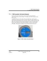
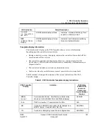
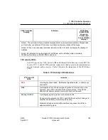
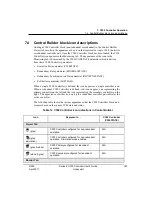
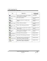
7.3. C300 faceplate display indications
C300 Faceplate
Display
Indicates…
C300 State
(PCMSTATE)
shown on
Station and
Control Builder
displays
Note 2: The controller is 'lonely' (cables disconnected or network related problem). Startup halts
until controller can obtain an IP address or validate an internally retained IP address.
Note 3: When a non-redundant controller reboots into the FAIL state, it assumes the backup IP
Address.
Note 4: SF indicates an on-line diagnostic soft failure, such as Battery status, Hardware
Watchdog timer timeout, IOLINK failure, and so on.
FTE activity LEDs
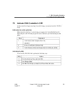
Each FTE port on the C300, Series 8 FIM and Ethernet Switch have one status LED. The
bi-color FTE A and B LEDs indicate connectivity (link present) and communication
activity (transmit and/or receive). Table 9 describes the indications of the FTE Status
LEDs.
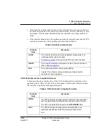
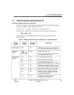
Table 9 FTE Activity LED Indications
FTE A and B
LEDs
Indicates…
RED
Link integrity check failed - No Ethernet signal detected, or cable is not
connected.
OFF
Link integrity is OK - Ethernet signal is present, but no activity on link.
Typically, every FTE node should show some activity. If the LED is
observed for several seconds, some activity should be seen.
Blinking
GREEN
Link integrity signal is present, with activity on link.
During normal operation the FTE A and B LEDs should be blinking at a
variable rate indicating normal network activity.
Moderate to high network traffic conditions may cause the LEDs to
appear as steady green.


