R500
April 2017
Series 8 C300 Controller User's Guide
Honeywell
85
4. C300 Controller Configuration
4.14. Add an I/O Channel to a Control Module
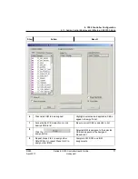
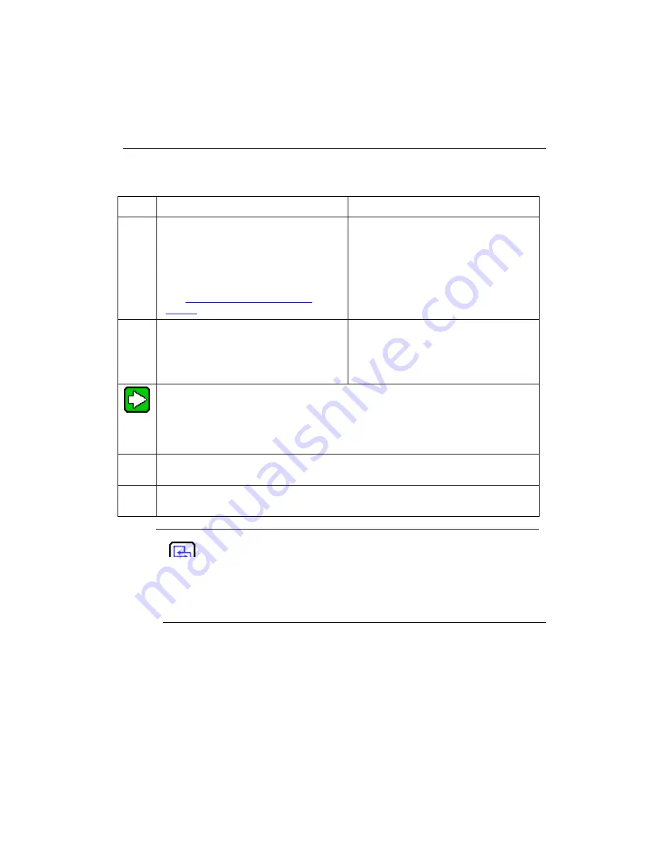
To add IO Channel blocks to a Control Module chart, perform the following steps.
Step
Action
Result
1
Make sure a Control Module (CM) chart
is open.
Double-click the CM in the Project Tree
to open your CM chart so function blocks
may be added.
The Control Module (CM) chart is open
so that function blocks may be added.
2
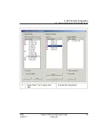
From the appropriate Library Tree group,
drag and drop the desired block (or
blocks) to the Control Module Control
Drawing (such as an AICHANNEL block
from the Series 8 group).
Desired block is shown in reverse video
on the tree.
The new function block appears on the
Control Module chart.
TIP
You can drag and drop Series 8 Input/Output Channel (IOC) blocks directly from IO
Ms added to the Project tab to the Control Module.
You cannot add IOC blocks to Control Modules already assigned to a Fieldbus
Interface Module (FIM).
3
Repeat Step 2 as many times as necessary to create the desired blocks for your
control strategy.
4
Create your control strategy by connecting the function blocks using the Insert wire
option.
REFERENCE - INTERNAL
For details to connect function blocks, see Connecting and disconnecting
blocks in the
Control Building Guide
.
If you are building a control strategy to include insertion points, refer to
Creating a strategy to use insertion points in the
Control Building
User’s
Guide.


